PLC ENGINEERING

Blog

Home

Blog

  • Allen-Bradley SLC 500: Battery Replacement, Program Backup & Parts Guide
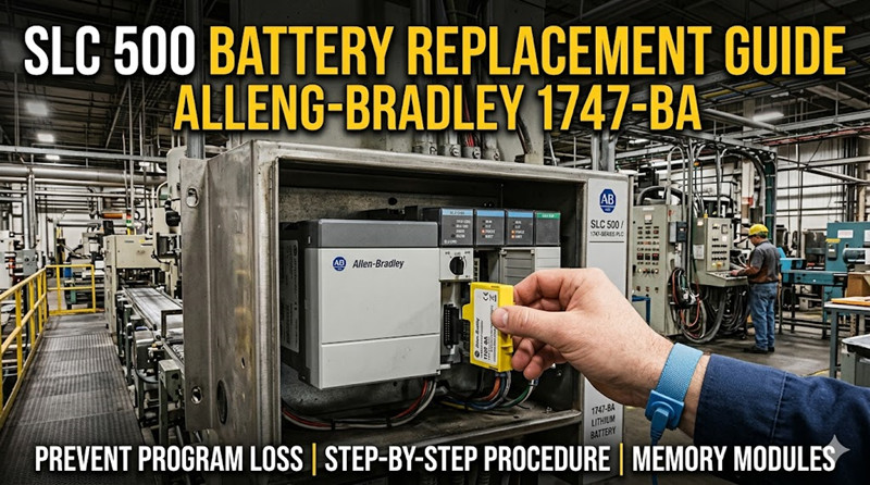
    Allen-Bradley SLC 500: Battery Replacement, Program Backup & Parts Guide Jun 22, 2026
    You walk into the plant on a Monday morning and the machine won't run. The SLC 500 CPU shows a solid FLT LED. The HMI is dark. You plug in your laptop, open RSLogix 500, and get nothing — the program is gone. A dead battery just wiped months of engineering work. This is the reality of the Allen-Bradley SLC 500 platform. These controllers have been running production lines since the early 1990s, and they depend on a simple lithium battery to retain the program when main power is off. When that battery dies, the ladder logic disappears. No backup means a full re-write from scratch. This guide covers everything you need to know about SLC 500 battery replacement: the correct part numbers, the exact step-by-step procedure, how to back up your program before the battery dies, and which spare parts to keep on the shelf. What Is the Allen-Bradley SLC 500?   The SLC 500 (Small Logic Controller) is a modular PLC platform introduced by Allen-Bradley (now Rockwell Automation) as a more capable alternative to the MicroLogix series. It uses the 1747-series backplane and supports a wide range of I/O modules, communication cards, and specialty modules. Despite being officially discontinued in the late 2000s, the SLC 500 remains in active service across thousands of facilities in North America and Latin America. Many plants have no immediate plan to migrate because the hardware works, the spare parts are still available on the secondary market, and a full migration to CompactLogix or ControlLogix is expensive and time-consuming. The key components of an SLC 500 system are: · CPU module (1747-L5xx series — 5/01, 5/02, 5/03, 5/04, 5/05) · Backplane (1746-Axx series — 4, 7, 10, 13, or 16 slots) · Power supply (1746-Px series) · I/O modules (1746-xxx discrete, analog, and specialty) · Memory module (1747-M1, M2, or M3 — optional program storage) · Battery (1747-BA or 1770-XYC) The battery is located inside the CPU or, in some chassis configurations, mounted externally. Without it, the CPU retains the program only as long as the chassis power supply is energized. A power interruption of any length means program loss.   SLC 500 Battery Replacement: Step-by-Step Procedure   Replacing the battery is straightforward, but skipping the backup step first is where people get burned. Here is the correct sequence.   1. Back Up the Program First   Before touching the battery, connect to the SLC 500 via RSLogix 500 and upload the program. Procedure: 1. Connect your programming laptop to the SLC 500 via the serial port (DF1/DH-485), DH+ module, or Ethernet (5/05 only). 2. Open RSLogix 500 and select Comms > System Comms. 3. Double-click the processor node to go online. 4. Go to Comms > Upload and select the correct processor type. 5. Save the uploaded file (`.RSS` format) to a safe location — ideally three locations: local machine, network drive, and USB stick. If the battery is already dead and the program is gone, this step won't help. You'll need to restore from a previous backup or a memory module.   2. Identify the Correct Battery   Two battery part numbers are compatible with the SLC 500: Part Number | Description | Typical Life 1747-BA | Standard SLC 500 battery assembly (BA = Battery Assembly) | 2-5 years 1770-XYC | NEMA 4/4X external battery housing and cable | 2-5 years Both use the same 3.6V lithium thionyl chloride (LiSOCl2) chemistry — the same cells used in industrial memory backup applications worldwide. The 1747-BA is a direct-fit battery that plugs into the CPU front panel. The 1770-XYC is a remote-mounted battery pack with a cable, used when the CPU is in a sealed enclosure or when the battery needs to be accessible without opening the main cabinet. The 1747-BA is the part you want for standard installations. It's widely available from Rockwell Automation distributors and industrial electronics suppliers. Expect to pay around $30–60 depending on the source.   3. Battery Location by CPU Type   Where the battery lives depends on which SLC 500 processor you have: SLC 5/01, 5/02 (1747-L511, L514, L524, L531): The battery is inside the CPU housing. Remove the small door on the front panel — the battery connector is behind it. These are the oldest processors and have the highest rate of battery failure because the units themselves are often 25+ years old. SLC 5/03, 5/04 (1747-L532, L541, L542, L543): Same arrangement — a battery door on the front of the CPU. The connector is keyed so you can't plug it in backwards. SLC 5/05 (1747-L551, L552, L553, L554): Identical front-panel battery access as the 5/03 and 5/04. The 5/05 is the most common processor still in service because it adds built-in Ethernet (10Base-T). 4. Replace the Battery   You need: · New 1747-BA battery · Small flathead screwdriver (optional, for battery door) · Antistatic wrist strap (recommended) Steps: 6. Leave the chassis power ON during battery replacement. The battery only backs up the RAM when main power is off. With power on, the CPU runs from the power supply and the battery circuit is inactive — you can swap it hot without losing the program. 7. Open the battery door on the CPU front panel using a flathead screwdriver or your thumbnail on the latch. 8. Disconnect the old battery connector by pulling the plug straight out. 9. Connect the new 1747-BA battery — the connector only fits one way. 10. Close the battery door. 11. Verify the CPU status. The BAT LED (if your processor has one) should turn off. On the SLC 5/03, 5/04, and 5/05, you can also check processor status under Processor Status in RSLogix 500. If you must replace the battery with main power OFF, you have approximately 30 minutes to swap the battery before the backup capacitor discharges and the RAM loses its program. Do not rely on this.   Memory Modules: The Real Backup Insurance   A 1747-BA battery is cheap insurance. A 1747 memory module is the real safety net. The Allen-Bradley 1747-M1, 1747-M2, and 1747-M3 are EEPROM-based memory modules that plug into the SLC 500 CPU and retain the entire program without any battery. They are available in different sizes: · 1747-M1: 64K memory module · 1747-M2: 128K memory module · 1747-M3: 256K memory module How they work: You save the program to the memory module from RSLogix 500 (Processor > Save to Memory Module). On power-up, the CPU checks for a memory module. If one is present and loaded with a valid program, the CPU can either load from the module or ignore it — the behavior is configurable via the module's write-protect switch. Recommendation: Install a 1747-M2 or M3 in every SLC 500 chassis you maintain. Even if the battery dies catastrophically and the RAM is wiped, the CPU can reload the program automatically from the memory module on the next power cycle. This single $100–200 part has saved more production shifts than any battery ever will.   SLC 5/01 vs 5/02 vs 5/03 vs 5/04 vs 5/05: What You Need to Know   If you're maintaining SLC 500 systems, you need to understand the differences between the CPU models.   SLC 5/01 (1747-L511, L514)   · Entry-level processor: limited instruction set, no real-time clock · RS-232 port (DH-485 protocol) · Max 4096 I/O points · Memory: 4K or 8K · Best for: simple machine control, conveyor logic, packaging   SLC 5/02 (1747-L524, L531)   · Added real-time clock, additional instructions (FAL, FSC, PID) · RS-232 port (DH-485) · Max 4096 I/O · Memory: 8K or 16K · Best for: moderate complexity applications with timing and sequencing   SLC 5/03 (1747-L532)   · Major step up: added RS-232 DF1 full-duplex protocol, flash OS upgrade capability · Real-time clock with battery backup · Memory: 16K or 32K · Faster execution than 5/01 or 5/02 · Best for: batch processes, more complex logic   SLC 5/04 (1747-L541, L542, L543)   · Added DH+ (Data Highway Plus) network port — critical for remote I/O and peer-to-peer communication with PLC-5 and ControlLogix · Memory: 16K to 64K · Best for: distributed control systems, multi-processor applications   SLC 5/05 (1747-L551, L552, L553, L554)   · Added built-in 10Base-T Ethernet (EtherNet/IP) · Memory: 16K to 64K · Can communicate via serial, DH-485, or Ethernet · Most common processor still in active service · Best for: any application needing Ethernet connectivity without an additional 1747-KE or 1747-AIC module   Chassis Types (1746-Axx Backplane)   All SLC 500 I/O modules and CPUs mount on a 1746-series backplane. Available sizes: Chassis | Slots | Typical Use 1746-A4 | 4 slots | Small panel, single-machine control 1746-A7 | 7 slots | Medium panel with mixed I/O 1746-A10 | 10 slots | Larger system with analog and specialty modules 1746-A13 | 13 slots | Large system, distributed I/O racks 1746-A16 | 16 slots | Maximum expansion without remote chassis Chassis are interchangeable — you can move a CPU and I/O between any 1746-Axx backplane as long as the power supply rating is adequate.   Communication Networks   The SLC 500 supports three major communication protocols: DH-485 (Data Highway 485): The native protocol for SLC 500. Uses a 4-wire RS-485 interface. Maximum 32 nodes, 4000 ft total cable length. Supported by all SLC 5/01 through 5/05 processors. Requires the 1747-PIC (PCMCIA Interface Card) or 1747-UIC (USB Interface Converter) to connect a modern laptop. DH+ (Data Highway Plus): Available only on the SLC 5/04. High-speed token-passing network. 57.6 Kbps standard, up to 230.4 Kbps. Used in larger Rockwell automation systems for PLC-to-PLC communication and SCADA integration. EtherNet/IP: Built-in on the SLC 5/05 or available as an add-on via the 1747-KE (Ethernet bridge module) for other processors. EtherNet/IP is the standard for modern industrial Ethernet — the 5/05 uses 10Base-T (10 Mbps), which is slow by modern standards but perfectly adequate for program uploads/downloads and HMI communication.   Pricing & Availability: Where to Find Parts   The SLC 500 is discontinued by Rockwell Automation, but parts are far from impossible to find.   Batteries (Easy to Find)   The 1747-BA and 1770-XYC are still manufactured by third parties and widely stocked. Rockwell also still produces the 1747-BA. Expect to pay $30–60. They are available from: · Rockwell distributors (Graybar, Rexel, Wesco, Motion Industries) · Industrial supply houses (McMaster-Carr, AutomationDirect, Radwell) · eBay and surplus sellers (prices vary wildly — verify condition)   CPUs and I/O Modules (Getting Scarce)   New-old-stock CPUs command a premium ($200–800 depending on model). The SLC 5/05 is the most expensive due to Ethernet demand. Used modules are available from: · Radwell International: Full inventory, tested, warranty · PLC Center: Specializes in Allen-Bradley surplus · eBay: High risk of counterfeit or damaged modules — test everything   Memory Modules (Limited)   1747-M1, M2, M3 modules are harder to find than the CPUs themselves. The 1747-M3 (256K) is the most sought-after and the rarest. Plan to spend $100–250 for a tested module.   Chassis and Power Supplies (Abundant)   1746-Axx backplanes and 1746-Px power supplies are still easy to find at reasonable prices. These are the least failure-prone components in the system.   FAQ   Q: How long does the SLC 500 battery last?   A: Typical life is 2–5 years depending on ambient temperature and power-off time. Higher temperatures reduce battery life. Install a fresh battery every 3 years during preventive maintenance.   Q: Can I replace the SLC 500 battery with the power on?   A: Yes. In fact, this is the recommended method. With chassis power applied, the battery circuit is idle — you can swap the battery hot without losing the program. Leave the chassis energized.   Q: What happens if the SLC 500 battery dies?   A: If the chassis loses main power with a dead battery, the CPU's RAM is wiped and the program is lost. The CPU will show a FLT LED and will not run until the program is re-downloaded or loaded from a memory module.   Q: Can I use a standard CR123A or AA battery instead of the 1747-BA?   A: No. The 1747-BA uses a 3.6V lithium thionyl chloride cell with a specific connector and form factor. Using a non-approved battery can damage the CPU or create a fire risk. Use only 1747-BA or 1770-XYC.   Q: What is the difference between 1747-BA and 1770-XYC?   A: The 1747-BA is a direct-fit battery that plugs into the CPU front panel. The 1770-XYC is a remote-mount battery pack with a cable for NEMA 4/4X enclosures. Both use the same cell chemistry.   Q: Does the SLC 500 automatically load from the memory module on power-up?   A: It depends on the memory module's write-protect switch setting. If the switch is in the LOAD position, the CPU loads the program from the module at power-up, even if the RAM is empty. If in PROTECT position, the module only saves data from the CPU and does not auto-load.   Q: Will Rockwell Automation still repair my SLC 500 processor?   A: Rockwell discontinued repair services for most SLC 500 processors. Third-party repair shops like Radwell offer repair services with warranties. For critical applications, keep a spare processor on the shelf.   Q: How do I connect a modern laptop to an SLC 500?   A: For serial connections, use a 1747-UIC (USB Interface Converter) or a third-party USB-to-DF1 adapter. For 5/05 processors, use a standard Ethernet cable (straight-through or crossover depending on your switch). For DH+ (5/04), you need a 1784-PCMK PCMCIA card or a USB-to-DH+ converter.   Summary   The Allen-Bradley SLC 500 is a workhorse platform that refuses to retire. Keeping it running comes down to three things: 12. Back up your programs — upload and save `.RSS` files from every processor, and keep copies off the plant floor. 13. Replace the 1747-BA battery every 3 years — set a calendar reminder. A $40 battery is cheap compared to a lost program. 14. Install a 1747-M2 or M3 memory module — this is the single best upgrade you can make. It survives battery failure, power surges, and operator errors. For new systems, consider migrating to CompactLogix 5380 or ControlLogix 5580. But for the thousands of SLC 500 systems still running production today, a proper battery maintenance schedule and a memory module are all you need to keep the lines running. ------------------------------------------------------------------------------------------------------------------- 🏢 About TZ Tech   TZ Tech is a leading supplier of industrial automation, electrical, instrumentation, and telecommunications components. We specialize in sourcing ready-to-ship distributor stock, allowing us to offer highly competitive pricing and short lead times. Thanks to our extensive inventory, we can even source rare and discontinued parts that are hard to find elsewhere.   🛡️ Our Quality Commitment   We understand that quality is your top priority. Every component undergoes a strict screening and inspection process so you can buy with absolute confidence. For legacy or discontinued parts, we believe in complete transparency and will always provide an honest, accurate report on the product's condition. Plus, all brand-new parts come backed by a full 1-year warranty.   ✉️ Get in Touch     Have a project or a part you need? Send us your inquiry today! Our team is dedicated to providing a fast response within 6 hours (excluding weekends).

  • Siemens S7-300: Maintenance, Troubleshooting & Manuals Guide
    Siemens S7-300: Maintenance, Troubleshooting & Manuals Guide Jun 18, 2026
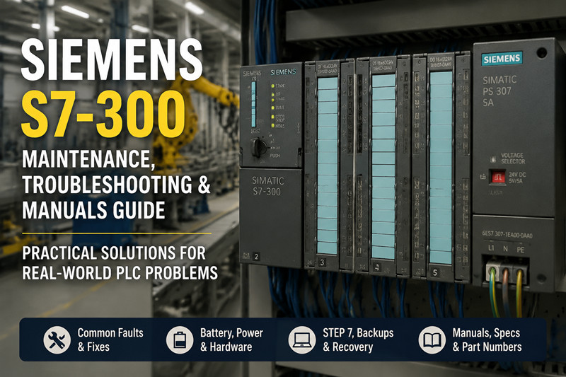
    The 3 AM Phone Call   The line went down at 2:47 AM. A Siemens S7-300 CPU on a bottling line had faulted with an LED pattern no one on the night shift had seen before — SF red, BF flashing, and the CPU in STOP mode. The plant electrician cycled power, no change. Swapped the memory card from a spare unit, no change. Three hours of lost production later, someone finally checked the backup battery voltage: 1.8 V. Dead battery on a CPU315-2 DP (6ES7 315-2AG10-0AB0) had corrupted the RAM-based user program. No backup file existed on the maintenance laptop. That scenario plays out in hundreds of factories every year, and almost all of it is preventable with basic Siemens S7-300 troubleshooting and maintenance.   The S7-300: Why It's Still Running Production Lines   Siemens launched the SIMATIC S7-300 family in the mid-1990s, and despite being officially designated for phase-out, these PLCs are still the backbone of manufacturing lines worldwide. The S7-300 sits between the micro-class S7-200 and the rack-based S7-400 — a modular mid-range controller capable of handling discrete manufacturing, process control, and motion applications. What makes the S7-300 stubbornly persistent is its installed base. A company that spent $50,000 on I/O modules, backplanes, and engineering in 2005 isn't going to forklift-upgrade a working line just because Siemens stopped actively selling the platform. Many S7-300 systems from the late 1990s and early 2000s are still running daily production, held together by knowledgeable maintenance teams and a healthy aftermarket parts supply. The most common CPU models still in service include the CPU315-2 DP (6ES7 315-2AG10-0AB0), the CPU314, and the CPU317-2 PN/DP for lines that need Profinet connectivity. Power comes from the PS307 (6ES7 307-1EA00-0AA0) series, and analog inputs are typically handled by the 8-channel SM331 module (6ES7 331-7KF02-0AB0). These specific model numbers matter because replacement parts, memory cards, and battery types all track back to them. For maintenance teams, the S7-300 presents a unique challenge: the hardware is aging, original documentation can be hard to find, and the engineering software (STEP 7) runs on operating systems that IT departments would rather not support. Knowing where to find a *siemens s7 300 manual* or a *siemens s7 300 manual pdf* before a breakdown happens is the difference between a 20-minute repair and a 20-hour ordeal.   Common Failure Modes in the Real World   Power Supply Issues — PS307 (6ES7 307-1EA00-0AA0)   The PS307 is the most commonly replaced component on an S7-300 rack. These switch-mode supplies fail with age — dried-out electrolytic capacitors, failing fans (on the 10 A version), and intermittent output under load. The warning signs are intermittent system resets, random SF LEDs on multiple modules, or a CPU that boots into STOP mode but runs fine after a power cycle. Test the PS307 with a multimeter at the output terminals. The 24 V DC versions should deliver between 24.0 V and 28.8 V under load. Anything below 22 V and the CPU will drop into STOP mode or behave erratically. If the supply passes voltage tests but you're still seeing intermittent failures, swap it. They're inexpensive relative to the downtime they cause.   CPU Faults — CPU315-2 DP (6ES7 315-2AG10-0AB0)   The CPU315-2 DP is a workhorse, but it has failure patterns worth knowing. The most common is a corrupted user program caused by a dead backup battery (6ES7 971-0BA00). When the battery voltage drops below approximately 2.5 V, the RAM-based program loses integrity. On the next power-up, the CPU goes to STOP with SF red and no amount of cycling will bring it back. The fix is reloading the program via MPI or Profibus from STEP 7 — assuming someone saved a backup. If no backup exists, you're looking at reverse-engineering logic from a working sister machine or paying for a full re-commission. Other CPU failure modes include Profibus communication faults (BF LED flashing or solid red), which are usually wiring or connector issues at the Profibus DP plug rather than the CPU itself. Try swapping the bus connector before replacing the CPU.   Memory Card Failures   The S7-300 uses MMC (MultiMediaCard) format memory cards for program storage. These cards have a limited write-cycle life, and cards from the early 2000s are now reaching end-of-life. Symptoms include the CPU failing to load the program from the card, CRC errors during boot, or the card being recognized in one CPU but not another. The original Siemens MMCs are discontinued and expensive on the secondary market. Third-party equivalents exist, but reliability is inconsistent. A better strategy is to maintain working backups on a laptop and use the memory card slot as a boot medium, not primary program storage.   I/O Module Faults — SM331 (6ES7 331-7KF02-0AB0)   Analog modules are the most sensitive to electrical noise and wiring errors. The SM331 8-channel AI module frequently fails when field wiring shorts 24 V to a signal input channel. Channel diagnostics LEDs (if equipped) or the SF group fault LED will light up. The fix is usually replacing the module, but always check the wiring first. A quick continuity test between each signal wire and ground will catch the 90% case. For more detailed *plc siemens s7 300 troubleshooting* approaches, the PLC section on tztechio.com has compatibility data and spare parts cross-references that save hours of manual research.     Deep Dive: Software, Batteries, Firmware, and Backups   STEP 7 Software Compatibility   The S7-300 programs are engineered using Siemens STEP 7. The critical compatibility table: STEP 7 Version | Supports | Windows STEP 7 V5.4 | S7-300 all CPUs | XP, Vista STEP 7 V5.5 | S7-300 all CPUs | Win7 (32/64) STEP 7 V5.6 | S7-300 all CPUs | Win7, Win10 (64-bit) TIA Portal V13+ | S7-300 (limited) | Win7, Win10 The original STEP 7 Classic (V5.x) is the safest choice for S7-300 work because TIA Portal's support for S7-300 is limited and certain older CPU firmware versions are not fully compatible. TIA Portal V13 through V17 can handle S7-300 CPUs with firmware V3.x and above, but if you're supporting a machine from 2003 running firmware V2.x, you need STEP 7 Classic. Finding a working *siemens step 7 300 manual* or a *siemens s7 300 manual programming* PDF is essential for anyone maintaining these systems. The official Siemens support portal still hosts many of these documents, but the search filters can be tricky. Use the exact model number as the search term for best results.   Battery Replacement — 6ES7 971-0BA00   The S7-300 backup battery (6ES7 971-0BA00) is a 3.6 V lithium cell that maintains the user program in RAM when the main power is off. Siemens recommends replacement every 3-4 years. In practice, most plants ignore this until the CPU loses its program. Replacement procedure: 1. Put the CPU in STOP mode. 2. Note the battery indicator — the yellow BATF LED means low battery. 3. Open the battery compartment door on the front of the CPU. 4. Remove the old battery (observe polarity). 5. Insert the new battery — 6ES7 971-0BA00 or any compatible 3.6 V lithium cell with the correct connector. 6. Power cycle the system to verify the program loads correctly. 7. Document the replacement date on the cabinet door. The battery only maintains the RAM when the PLC is powered off. If the system stays powered on continuously, a dead battery causes no problems until the next planned or unplanned shutdown. Always replace the battery during a scheduled outage — never hot-swap it on a running line unless you have a verified backup file.   Firmware Updates   S7-300 CPUs rarely need firmware updates unless you're adding new hardware modules or resolving a specific bug. Firmware files are available from the Siemens Industry Online Support portal. The update process uses a memory card: 8. Download the firmware update file (a .UPD file for S7-300). 9. Copy it to an MMC card. 10. Insert the card in the CPU while it's powered on. 11. The CPU detects the firmware file and prompts an update. 12. Confirm, wait for completion (CPU restarts automatically). Firmware updates wipe the user program. Always back up the program before updating firmware.   Backup Procedures   A proper S7-300 backup strategy has three layers: · Layer 1: Full program upload from CPU to STEP 7 (File > Upload Station to PG). Save the entire project. · Layer 2: An MMC card with the current program, stored in a static-safe bag inside the cabinet. · Layer 3: An offline archive of the STEP 7 project (zipped or saved to a network share). Label every backup with the machine name, date, and CPU firmware version. The worst time to discover that a backup is from 2017 is when your CPU fails in 2025.   Pricing & Availability of S7-300 Spare Parts   Siemens officially discontinued the S7-300 family for new sales, though support continues for existing installations. This means new-old-stock (NOS) genuine Siemens parts command premium prices: Component | Typical Price Range (Second Market) CPU315-2 DP (6ES7 315-2AG10-0AB0) | $400 – $1,200 PS307 5A (6ES7 307-1EA00-0AA0) | $100 – $300 SM331 AI 8x12bit (6ES7 331-7KF02-0AB0) | $200 – $600 Backup Battery (6ES7 971-0BA00) | $15 – $40 MMC 64KB | $30 – $100 Used and refurbished parts are available from industrial surplus dealers, eBay Industrial, and specialized PLC distributors. Quality varies significantly. A refurbished unit from a reputable supplier that tests under load is worth the 20-30% premium over untested "as-is" surplus. Budget-conscious plants should identify the top 5 most failure-prone modules on each S7-300 system and keep spares on the shelf. For most lines, that means one spare PS307, one spare CPU, one spare of each I/O module type, and two spare batteries. The inventory cost is usually under $2,000 per line and pays for itself the first time a module fails at 3 AM. Frequently Asked Questions   Q: Can I program an S7-300 without STEP 7? A: No. The S7-300 requires Siemens STEP 7 (Classic V5.x or TIA Portal) for programming, configuration, and diagnostics. Open-source alternatives like OpenPLC do not support S7-300 hardware. Q: What does the red SF LED on my CPU315-2 DP mean? A: The SF (System Fault) LED indicates a hardware fault, a programming error, or a communication problem. Connect STEP 7 and check the diagnostic buffer (PLC > Module Status > Diagnostic Buffer). The buffer shows the exact error with a timestamp. Q: How long does the S7-300 backup battery last? A: Siemens rates the 6ES7 971-0BA00 battery for 3-4 years in storage or unpowered PLC. In practice, if the PLC is powered on continuously, the battery lasts its full shelf life (about 5 years from manufacture date). Replace it every 3 years during planned maintenance. Q: My S7-300 CPU won't boot after a power outage. The SF LED is solid red. What now? A: 90% chance it's a corrupt program from a dead backup battery. Replace the battery, then reload the program from STEP 7 or an MMC card. If the memory card has the program, insert it and power cycle. The CPU should copy the program from the MMC to RAM. Q: Is the S7-300 still supported by Siemens? A: Siemens announced the phase-out of the S7-300 family, but the product is not fully discontinued for support. The Siemens Industry Online Support portal still provides manuals (including *siemens s7 300 manual* and *siemens simatic s7 300 manual* PDFs), firmware updates, and technical support for existing installations. Q: Can I replace an S7-300 with a newer Siemens PLC without rewiring? A: Direct drop-in replacement is not possible. The S7-1200 and S7-1500 families use different form factors, backplane connections, and engineering software (TIA Portal only). Replacement requires a new panel layout, rewiring, and program migration. Budget at least 40 engineering hours per CPU for a full migration. Q: What's the cheapest way to get a *siemens s7-300 pdf* manual? A: All official S7-300 manuals are free from the Siemens Industry Online Support portal (support.industry.siemens.com). Search by exact model number (e.g., "6ES7 315-2AG10-0AB0 manual") for the most relevant results. Third-party document aggregation sites often charge for the same PDFs that Siemens hosts for free. Q: How do I know if my SM331 analog module is faulty? A: Check the SF group fault LED. Then disconnect all field wiring and supply a known 4-20 mA or 0-10 V signal from a calibrator. If the channel reads correctly, the module is fine and the problem is in the field wiring. If it reads incorrectly or shows no signal, the channel is likely damaged, typically from overvoltage or short-circuit conditions.   Maintenance Checklist Summary   A quarterly S7-300 maintenance pass takes 30 minutes per rack and catches the most common failure modes before they cause downtime: 13. Inspect PS307 output voltage under load (24-28.8 V DC). 14. Check CPU BATF LED — replace battery if yellow. 15. Verify all I/O module SF LEDs are off. 16. Open STEP 7 and read the CPU diagnostic buffer — clear old entries. 17. Verify the MMC card is seated properly. 18. Upload and archive the current program. 19. Document any LED patterns or error messages observed. 20. Check Profibus connectors for tightness and correct termination resistors. Most S7-300 failures are not sudden. They announce themselves through intermittent faults, borderline power supply voltages, or LEDs that maintenance crews tuned out months ago. A disciplined approach to monitoring, documentation, and spare parts inventory turns the S7-300 from a reliability risk into a known quantity — one that keeps running until the plant decides it's time to modernize.
  • Danfoss VFD-PLC Communication: Setup Guide for Common Protocols
    Danfoss VFD-PLC Communication: Setup Guide for Common Protocols Jun 16, 2026
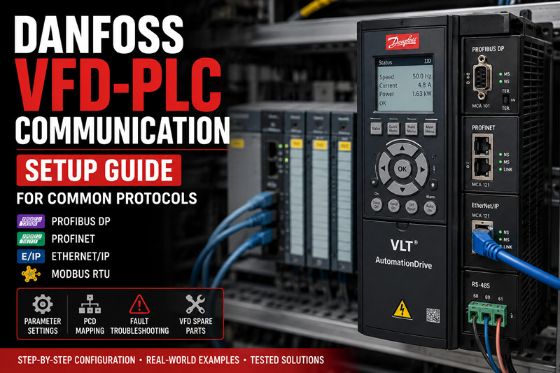
    The Frustration Is Real You've wired everything correctly. The Danfoss VLT drive powers up, the motor spins, and the PLC is online. But the second you send a write command over the fieldbus, you get a comm fault — or worse, the drive ignores you completely. I've been there. Parameter 8‑30 shows "No Message," the green Fieldbus LED blinks an angry pattern, and the production manager is staring over your shoulder. This article is the cheat sheet I wish I'd had on my first dozen Danfoss integrations. We'll cover the four major protocols — PROFIBUS, PROFINET, EtherNet/IP, and Modbus RTU — with the exact parameter numbers, PCD mappings, and troubleshooting steps you need to get data moving reliably. The Basics: Danfoss VLT Series and Fieldbus Options Danfoss has produced several generations of VFDs under the VLT brand. The most common models you'll encounter in industrial settings are the VLT Micro Drive FC 51, VLT AutomationDrive FC 302, VLT AQUA Drive FC 202, and the newer VLT Midi Drive FC 280 and iC7 Series. For PLC integration, the FC 302 and FC 202 are the workhorses — they support the full suite of communication option cards and have the richest parameter sets.   Supported Fieldbuses Protocol | Typical Use Case | Option Card Required? Modbus RTU (RS‑485) | Legacy plants, simple SCADA, small PLCs | No — built into standard drives PROFIBUS DP | Siemens S7‑300/400, older plants | VLT PROFIBUS DP MCA 101 PROFINET | Siemens S7‑1200/1500, modern lines | VLT PROFINET MCA 120 or MCA 121 EtherNet/IP | Allen‑Bradley CompactLogix / ControlLogix | VLT EtherNet/IP MCA 121 Key point: If your drive is an FC 51, you're limited to Modbus RTU via the built‑in RS‑485 terminals (68, 69, 61). For the FC 302/202/280, you can add any of the option cards above. The iC7 series has integrated multi‑protocol Ethernet — no card required.   Communication Profile (CTW / MAV / PCD) Every Danfoss fieldbus implementation is built on the same foundation: a Control Word (CTW), a Reference / Main Actual Value (MAV), and a set of Process Data (PCD) words. You don't need to memorize every bit in the CTW — the critical ones are: · Bit 0: Start command · Bit 1: Reverse · Bit 2: Coast stop · Bit 3: No coast stop (quick stop) · Bit 7: Reset fault · Bit 8: Jog · Bit 15: Bus ramp stop / no ramp stop selection The Status Word (STW) mirrors these: Bit 0 = Ready, Bit 1 = Ready to Run, Bit 2 = Running, Bit 3 = Running at Reference, Bit 7 = Fault, etc. Get comfortable with these — they're identical across all protocols.   The Real World: Protocol-by-Protocol Setup   1. Modbus RTU Modbus RTU is the simplest and most forgiving. It's built into every VLT drive on terminals 68 (TX+/RX+) , 69 (TX-/RX-) , and 61 (common) . Parameter checklist for FC 302: · 8‑30 Protocol = `Modbus RTU` · 8‑31 Address = set your bus address (1‑247) · 8‑32 Baud Rate = match your master (9600, 19200, 38400) · 8‑33 Parity / Stop Bits = `Even, 1 Stop` (common) or `No Parity, 2 Stop` · 8‑35 Minimum Response Delay = 10 ms (start here; increase if collisions occur) · 8‑36 Maximum Response Delay = 100 ms Writing to the control word: Modbus holding register address 0x2000 (dec 8192). Reference value goes into 0x2002 (dec 8194). Reading actual speed? Register 0x2100 (dec 8448) for the status word and 0x2102 (dec 8450) for the main actual value. Common mistake: You send 0x047F to register 0x2000 expecting the drive to run, and nothing happens. Check 8‑30 — if it's set to FC Profile instead of Modbus RTU, the drive won't interpret the control word correctly. Also verify 8‑50 Coasting Select isn't overriding your start command.   2. PROFIBUS DP PROFIBUS gets a bad rap for being fiddly, but once the GSD file is loaded and the baud rate locks, it's rock solid. Hardware: · VLT PROFIBUS DP MCA 101 option card · BUS terminals: A‑line (red), B‑line (green), shield connected at both ends · Termination resistors ON at the two physical ends of the segment Parameter setup: · 8‑30 Protocol = `PROFIBUS DP` · 8‑31 Station Address = match your HW DIP switches (or parameter setting if software addressing is enabled) · 8‑32 Telegram Selection = `Standard Telegram 1` (2 words: CTW+MAV) or `Standard Telegram 20` (6 words: CTW+MAZ+4 PCD). For most speed‑controlled applications, Telegram 1 is enough. · 8‑02 Control Source = `Digital Input and Control Word` · 8‑03 Control Word Timeout Time = 1.0 s (if no message in 1 second, trip) GSD file: Download DANF0653.GSD or DANF06B3.GSD from Danfoss's site and import into TIA Portal or Step 7. The slot configuration is straightforward — slot 1 = control word, slot 2 = reference, slots 3‑6 = PCD. PCD mapping (Telegram 20): If you need to read motor current (parameter 16‑14) or DC link voltage (parameter 14‑30), map them via 8‑50* to 8‑53* (for read PCDs) and 9‑50* to 9‑53* (for write PCDs). Example: · 8‑50 PCD 1 Read = `16‑14 Motor Current` · 8‑51 PCD 2 Read = `14‑30 DC Link Voltage`   3. PROFINET VLT PROFINET MCA 120 (older) or MCA 121 (current). The process is nearly identical to PROFIBUS conceptually, but simpler because PROFINET handles addressing automatically via DCP. Parameter setup: · 8‑30 Protocol = `PROFINET IO` · 8‑70 IO‑Cycle Time = 4 ms (default; lower = faster but more CPU load) · 8‑72 PROFINET Station Name = set this via the VLT Memory Card tool or the drive keypad (or use DCP tool like PRONETA) · 8‑02 Control Source = `Control Word` GSDML file: Import GSDML‑V2.33‑Danfoss‑MCA121‑2023xxxx.xml (version varies). The standard telegram sizes match PROFIBUS: Telegram 1 (2 words), Telegram 20 (6 words), Telegram 21 (10 words), etc. PROFINET-specific tips: 1. Station Name must match exactly — case-sensitive. If the PLC can't find the drive, use Siemens PRONETA to scan the network and rename the device. 2. IO‑Cycle Time: Don't go below 2 ms unless you've verified the PLC's DR cycle can handle it. I've seen TIA Portal reject anything under 1 ms on older CPUs. 3. Watchdog: Parameter 8-03 still applies. Set to 2x your IO‑Cycle Time.   4. EtherNet/IP For Allen‑Bradley users, the VLT EtherNet/IP MCA 121 card makes the drive appear as a standard CIP device. You'll need the EDS file from Danfoss. Parameter setup: · 8‑30 Protocol = `EtherNet/IP` · 8‑70 IO‑Cycle Time = RPI setting in the PLC (default 10 ms is fine) · 8‑72 IP Address Assignment = `DHCP`, `Static`, or `BootP` (match your plant's IP scheme) · 8‑74 Subnet Mask and 8‑75 Default Gateway — set if static · 8‑02 Control Source = `Control Word` Studio 5000 / Logix Designer setup: 4. Download the EDS file from Danfoss and register it via `Tools > EDS Hardware Installation Tool`. 5. Add the drive to the IO tree under your Ethernet bridge. The default assembly instances are: · Output Assembly (PLC → Drive): Instance 101 (4 words: CTW + Ref + 2 PCD) · Input Assembly (Drive → PLC): Instance 102 (8 words: STW + MAV + 6 PCD) 6. Map the data to controller tags. I typically create a UDT with `Drive_CTW`, `Drive_Ref`, `Drive_STW`, and `Drive_MAV`. Common issue: If the drive shows "No Connection" in the module status, check that the RPI in the PLC matches 8‑70. Also verify the IP address isn't duplicated — ping it from a laptop before commissioning.   Deep Dive: Parameter Tuning and Troubleshooting Comms Faults   PCD Read/Write Configuration (FC 302) This is where most people get stuck. The PCD mapping lets you read or write any drive parameter over the fieldbus beyond the standard CTW/MAV. Read PCDs (drive → PLC): 8‑50 through 8‑53 (up to 4 read PCDs in Telegram 20). Each parameter slot expects the parameter number of the data you want to read. Write PCDs (PLC → drive): 9‑50 through 9‑53. Want the PLC to set the digital output terminal? Map 5‑40 Function of Digital Out to a write PCD. Example: You want to read motor frequency (16‑12) and motor current (16‑14) back from the drive: ` 8‑50 PCD 1 Read Configuration  =  16‑12  motor frequency  [Hz] 8‑51 PCD 2 Read Configuration  =  16‑14  motor current     [A] ` Now the PLC reads STW + MAV + PCD1 + PCD2. The PCD values appear in the telegrams after the MAV slot. Scaling is handled by the parameter's defined unit — 16‑12 is in 0.01 Hz, 16‑14 is in 0.1 A.   Troubleshooting the Top 5 Comms Faults Fault / Symptom | Likely Cause | Fix Alarm 34 / Bus Fault | No valid fieldbus message received within 8‑03 timeout | Check cable, master state, and that 8‑30 matches your hardware Drive doesn't start (no rotation) | Control Word bits not set correctly, or 5‑12/5-13 terminal conflicts | Set 8‑02 Control Source to `Control Word` exclusively; disable any digital input start commands Alarm 22 / Hardware fault | PROFIBUS: wrong baud rate or duplicate station address | Force baud via GSD file; verify address uniqueness PROFINET device not found | Station Name mismatch or IP conflict | Use PRONETA to scan and reassign; reboot the drive after renaming EtherNet/IP "No Connection" | RPI mismatch or EDS file version | Match 8‑70 RPI to PLC connection RPI; download latest EDS from Danfoss The 8‑50 Trap I've seen engineers spend hours troubleshooting because they entered 8‑50 PCD 1 Read Configuration as 16‑12 but forgot to set 8‑32 Telegram Selection to Standard Telegram 20 (or higher). With Telegram 1, the drive only sends CTW+MAV — any PCD slots are simply ignored. Always verify your telegram size matches your PCD count.   Bus Termination Done Right For RS‑485 (Modbus RTU) , the built‑in termination resistor is enabled via 8‑36 in some drive variants, or by a physical DIP switch on the control card. For PROFIBUS, use the DIP switches on the MCA 101 card — position ON for the end devices. For PROFINET and EtherNet/IP, no bus termination is needed (standard Ethernet wiring rules apply: star topology, cable run < 100 m per segment). Pricing & Availability: VFD Modules and Option Cards At TZTech.io, we stock a wide range of Danfoss VFD units and communication option cards, including hard‑to‑find legacy variants. Part Number | Description | Typical Lead Time VLT FC 302 (various kW) | AutomationDrive, 0.25–75 kW | In stock VLT FC 202 (various kW) | AQUA Drive, pump/fan applications | In stock MCA 101 | PROFIBUS DP option card | 3–5 business days MCA 120 | PROFINET option card (older) | Limited stock MCA 121 | PROFINET / EtherNet/IP option card (current) | In stock VLT 2800 | Legacy VFD (discontinued — check availability) | Contact us All parts are tested before shipping. We ship globally to the Middle East, Americas, and Europe. Need a replacement Danfoss VFD for a line‑down situation? Browse our Danfoss inventory or check our full VFD selection. For complete PLC integration packages, see our PLC spare parts section. FAQ — Real Questions from Engineers and Buyers   Q1: Can I use Modbus RTU and a fieldbus option card at the same time? No — the built‑in RS‑485 port and an option card share the same internal communication bus on most FC 302 drives. Only one fieldbus protocol can be active at a time. Set 8‑30 to the protocol you're using.   Q2: My Danfoss VLT FC 302 shows "Alarm 34" immediately after I send a start command. What's wrong? Alarm 34 is a bus timeout. Check 8‑03 Control Word Timeout Time — if it's set lower than your PLC's update rate, the drive trips. Increase it to 2–5 seconds for testing, then dial it back to 2x your bus cycle time in production.   Q3: Do I need a 24 V DC backup supply to keep fieldbus communication alive when the mains is off? Yes, if you want to monitor the drive or see the last fault code after a power loss. Wire 24 V DC to terminals 35 (+) and 39 (-) on the FC 302 control card. Without it, the option card loses power with the mains.   Q4: The drive runs from the terminal panel but ignores bus commands. What did I miss? 8‑02 Control Source defaults to Digital Only on many FC 302 drives. Change it to Control Word Only to force the drive to accept start/stop commands exclusively from the fieldbus. If you need both (local pushbutton + bus), set it to Digital Input and Control Word and configure the digital inputs for "Bus Start" in 5‑12.   Q5: What's the maximum cable length for Danfoss PROFINET? Standard PROFINET cable: 100 m per segment between switches. If your drive is farther from the switch than that, install a PROFINET repeater or a media converter (fiber optic). For Modbus RTU, max is 1200 m at 9600 baud — drop to 400 m at 38400 baud.   Q6: I have a discontinued VLT 5000 / VLT 2800. Can I still get a communication card for it? The VLT 5000 uses the Profibus DP V1 card (part no. 176Fxxxx), and the VLT 2800 uses the SI‑P or SI‑M cards. These are discontinued but we occasionally have tested used units in stock. Contact us with your exact model number and we'll check availability. --- *Need a replacement Danfoss VFD or comm card fast? Shop Danfoss VFD spare parts at TZTech.io — tested, shipped globally, and backed by real engineers who know the hardware.*
  • Omron C200H End-of-Life: Battery Replacement, Programming Cable, Software & Migration Guide
    Omron C200H End-of-Life: Battery Replacement, Programming Cable, Software & Migration Guide Jun 15, 2026
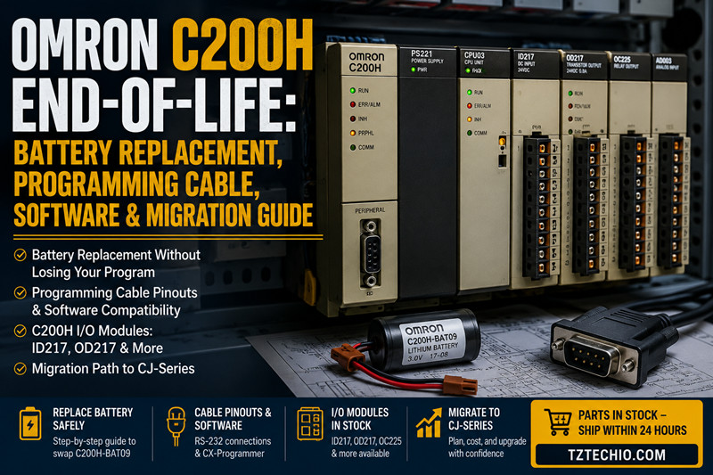
    The Omron C200H programmable logic controller was once a backbone of industrial automation across factories worldwide. Officially discontinued by Omron for years now, maintenance engineers supporting these legacy systems face a cold reality: spare parts are drying up, support documentation is scattered, and plant managers are pushing for upgrades. If you are still running a C200H on your production floor — and many are — this guide is for you. We cover battery replacement without losing your program, programming cable pinouts, software compatibility, current module availability, and a realistic migration path to the CJ-series.   1. Battery Replacement: C200H-BAT09 and How to Swap Without Losing the Program The C200H uses a lithium backup battery (Omron part number C200H-BAT09) to retain the user program and memory in the CPU when main power is off. Typical battery life is 5 years under normal ambient conditions. When the battery voltage drops, the CPU's ALARM LED flashes or the "BAT LOW" indicator appears on the programming console. Replace it promptly — a dead battery during a plant shutdown means a blank CPU on restart. Where to buy: The C200H-BAT09 is discontinued by Omron but still available from specialty automation distributors and surplus suppliers. At tztechio.com, we stock genuine Omron C200H-BAT09 units. Avoid generic lithium cells that lack the connector and voltage regulator; an off-spec battery can leak or overheat inside the CPU housing. Step-by-step replacement procedure: 1. Power on the PLC and connect a programming tool (handheld programmer or CX-Programmer via cable). 2. Upload the entire program to your programming software and save a backup to disk. 3. Keep main power ON throughout the swap — this powers the RAM from the power supply, not the battery. 4. Open the CPU front cover. Locate the battery connector on the top-right of the main board. 5. Gently unplug the old C200H-BAT09 connector. Remove the battery from its holder. 6. Insert the new C200H-BAT09 and plug the connector firmly. Observe polarity: red wire to +, black wire to —. 7. Close the cover. Verify on the programming tool that memory is intact. Clear the battery error flag if needed (CX-Programmer: in PLC status, click "Clear Battery Error"). 8. Record the replacement date on the label inside the CPU door. Critical warning: Never replace the battery with power off. Even the supercapacitor backup on some C200H CPU revisions drains within 20 minutes. If power removal is unavoidable, you must restore power within 60 seconds of battery disconnect.   2. Programming Cable & Software: Cable Pinout and CX-Programmer Compatibility Programming the C200H requires a peripheral cable and compatible software. The standard connection is RS-232C via the peripheral port (a 9-pin D-sub female on the CPU or an optional peripheral port adapter). Cable types and pinout: · C200H-CN221 (Omron original): Connects the C200H peripheral port to a 9-pin RS-232 serial port on a PC. Pinout: 2→2 (RXD), 3→3 (TXD), 5→5 (GND). No handshaking lines needed for most operations. · USB-to-RS232 adapters: These work if the adapter uses a genuine FTDI or Prolific PL2303 chipset. Avoid cheap knockoffs — they introduce transmission errors that can corrupt the program during upload/download. · CQM1-CIF02 (peripheral-to-RS232 adapter): Required if your C200H CPU has the older 8-pin round peripheral connector. Use this adapter plus a standard straight-through RS-232 cable. Software options: · CX-Programmer (version 3.0 through 9.x): Fully supports the C200H. Newer CX-Programmer versions (9.5 and later) run on Windows 10/11 but require the legacy driver mode. Set the PLC model to "C200H" and the network type to "SYSMAC WAY" or "Toolbus." · SYSWIN (older Omron software): Works but is limited to very old Windows versions. Not recommended. · SYSMAC-CPT: Covers C200H programming but is obsolete. Only use if you already have a license. · Software download: CX-Programmer is still sold by Omron under the FA Integrated Tool Package. No free version exists. Some third-party sites offer "trial" versions — these are often malware. Purchase licensed software or work with a distributor that provides a license bundle. Communication settings: 9600 baud, 7 data bits, even parity, 2 stop bits (7, E, 2) — this is the default C200H SYSMAC WAY protocol. CX-Programmer auto-detects these settings in most cases. 3. Common Module Reference: ID217, OD217, and Other I/O Modules Despite the C200H being discontinued, many I/O modules remain available through surplus channels. The most requested modules are: Module | Type | Description C200H-ID217 | 16-point DC input | 24 VDC sink/source, 8 mA per point, removable terminal block C200H-OD217 | 16-point transistor output | 24 VDC, 0.5 A per point, short-circuit protection C200H-OC225 | 16-point relay output | 2 A per point, isolated commons, replaceable relays C200H-AD003 | Analog input module | 4-channel, 1–5 V / 4–20 mA, 12-bit resolution C200H-DA004 | Analog output module | 4-channel, 1–5 V / 4–20 mA, 12-bit resolution C200H-CT021 | High-speed counter | 2 channels, 50 kHz, encoder input Availability: C200H-ID217 and C200H-OD217 are the highest-demand modules because DC I/O racks endure the most electrical stress in the field. We regularly replenish stock of both. Relay output modules (OC225) are also popular in older conveyor and packaging lines that do not need high-speed switching. What to check before buying used modules: · Inspect the backplane connector pins for bending or corrosion. · Test the LED indicators with a 24 VDC source on inputs. · For analog modules, request a calibration report or test values.   4. Migration Path: C200H → CJ-Series – What to Consider Eventually, every C200H installation reaches a point where a module fails, spare parts cost more than a new PLC, or the plant loses a qualified programmer. The natural upgrade path is the Omron CJ-series (CJ1, CJ2, or the newer NJ/NX series for motion control). Why CJ-series? · Same programming environment (CX-Programmer) — your engineers do not need retraining. · Significantly faster scan times (0.04 μs per basic instruction vs. 0.15 μs on C200H). · Compact footprint — up to 70% smaller than a C200H rack. · Current production, full warranty, and global support. Wiring compatibility — the hard truth: C200H and CJ-series I/O modules use different backplane architectures and connectors. You cannot simply pull a C200H-ID217 out of the old rack and plug it into a CJ-series base. The wiring must be re-terminated or adapted. Practical migration steps: 9. Inventory your rack: Document every module, slot position, and terminal assignment. Create a wiring map. 10. Choose a CJ-series CPU based on I/O count and program size. A CJ2M-CPU31 handles most mid-sized C200H replacements. For larger installations, the CJ2H-CPU64 provides 160K steps and Ethernet/IP. 11. Select I/O modules: The CJ-series uses CJ1W-* modules (e.g., CJ1W-ID211 replaces C200H-ID217 function; CJ1W-OD211 replaces OD217). They offer the same electrical characteristics in a smaller form factor. 12. Rewrite the program — do not attempt a direct conversion. The CJ-series instruction set is a superset of the C200H, but addressing is different (I/O memory maps are completely restructured). CX-Programmer's "Convert PLC" tool is a starting point, but manual verification is mandatory. 13. Panel rework: The CJ-series uses a 32-point or 64-point terminal block system, not the C200H's individual module wiring. Plan for new terminal rail and wiring duct placement. 14. Commission offline: Test the new program on the CJ-series CPU with simulator mode before removing the old C200H from service. Migration cost breakdown (typical 64-I/O system): Item | Estimated Cost CJ2M-CPU31 + power supply + 4-slot base | $650–$900 CJ1W I/O modules (equivalent to existing C200H I/O) | $100–$250 per module Wiring labor (in-house, 16–24 hours) | $800–$1,800 Programming & commissioning | $500–$2,000 Total estimate | $2,050–$4,950 Compare this to the cost of a single failed C200H-OD217 during an unplanned outage, and the migration often justifies itself within one production cycle.   5. Pricing & Availability: Where to Find C200H Stock Now C200H parts are no longer manufactured, so the market is purely aftermarket and surplus. Here is what you can expect: · C200H-CPU01/03: $150–$300 (used, tested) · C200H-BAT09 battery: $25–$45 (new old stock) · C200H-ID217: $60–$120 (used, tested) · C200H-OD217: $70–$150 (used, tested) · C200H-OC225: $50–$100 (used, tested) · C200H-AD003: $100–$200 (used, calibration required) · C200H-RM001 (remote I/O master): $80–$180 At tztechio.com, we carry a curated stock of C200H modules, all bench-tested before listing. We also supply CJ-series systems at competitive prices for those ready to migrate. Check our PLC category and Omron section for current inventory. Pro tip: If you are buying C200H spares to keep a line running for another 2–3 years, purchase at least one spare power supply (C200H-PS201 or PS221) per rack. Power supply capacitors age and fail more frequently than CPU boards. 6. FAQ – Real Questions from Buyers Q: Can I use a standard CR17345 lithium battery instead of C200H-BAT09? A: The cell is the same size (CR17345), but the C200H-BAT09 includes a pre-attached connector with polarity-specific housing and a voltage regulator circuit. A bare cell without the regulator can damage the CPU board. Use the genuine part. Q: Does CX-Programmer work on Windows 10 with the C200H? A: Yes, CX-Programmer version 9.5 and later runs on Windows 10/11 64-bit. You must install the legacy USB/serial drivers in compatibility mode. If using a USB-to-RS232 adapter, install the adapter driver before connecting the PLC. Q: My C200H-OD217 outputs are stuck ON. Is the module bad or the CPU? A: First check if the output load is within the 0.5 A per-point limit. Overload kills the output transistor in a shorted state. Swap the module to a different slot; if the problem follows the module, replace it. If it stays on the same slot address, troubleshoot the CPU output table. Q: What cable do I need for a C200H CPU with an 8-pin round port? A: You need a CQM1-CIF02 peripheral-to-RS232 adapter plus a standard DB9 straight-through serial cable. Alternatively, the CS1W-CIF31 USB adapter (with 8-pin round connector) works on newer PCs that lack serial ports. Q: Is the C200H still supported by Omron for technical support? A: Omron no longer provides phone or email support for the C200H series. Your best resources are distributor technical teams, automation forums (PLCTalk.net, MrPLC.com), and our support line at tztechio.com for module-specific questions. Q: Can I mix C200H and CJ-series modules on the same backplane? A: No. The backplane bus architecture is completely different. Migration requires replacing the entire rack. However, you can keep the C200H running alongside a new CJ-series rack using a serial or Ethernet link in the same control panel during phased migration. ------------------------------------------------------------------------------------------------------------------ TZ Tech is a professional supplier for industrial automation and electrical parts, as well as some instrumentation, telecommunication parts. We mostly sell the ready stock of distributor, with competitive price and short lead time. Even discontinued parts we may also can supply as we have a large inventory here.    We understand what you concern, so we will ensure the quality. We strictly screen the components you require, so you don’t need worry about any quality issues with the goods you receive. For specialized parts that have long since been discontinued, we will sincerely inform you the actual condition of the goods. All brand new parts we will support 1 year warranty.     If you need any related parts, please feel free to send an inquiry. Our staff will support quick response within 6 hours. (except weekend here)
  • Functional Safety in PLC Systems: SIL Levels, Safety Relays, and Compliance Explained
    Functional Safety in PLC Systems: SIL Levels, Safety Relays, and Compliance Explained Jun 10, 2026
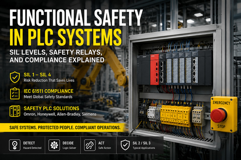
    Hook A safety system either works or it doesn't — and when it doesn't, people get hurt. That's the irreducible reality of industrial functional safety. But translating that reality into a PLC procurement spec means navigating SIL levels, IEC 61511, fail-safe I/O, and a market full of overlapping certifications that can make your head spin. In 2026, this isn't just an engineering concern. It's a legal one. Europe's NIS2 directive now covers manufacturing as critical infrastructure. Middle Eastern projects under Saudi Aramco and ADNOC standards mandate IEC 61511 compliance with specific SIL targets. Even in North America, where OSHA historically took a lighter touch on automation safety standards, insurance carriers are writing policy requirements that reference IEC 61508. This article cuts through the alphabet soup. By the time you finish it, you'll know which SIL level your application needs, which safety PLC families actually deliver it, and what the compliance paperwork looks like on the other side. The Basics   What Functional Safety Actually Means Functional safety is not the same as electrical safety. Electrical safety prevents shocks and fires — proper grounding, circuit protection, enclosures. Functional safety guarantees that when something goes wrong, the control system fails in a way that keeps people safe. A functional safety system has three jobs: detect a dangerous condition (the light curtain breaks), make a decision (stop the press), and execute that decision reliably (de-energize the motor contactor). The entire chain — sensor, logic solver, final element — must be designed so that no single component failure prevents the system from doing its job.   SIL: The Number That Defines Everything Safety Integrity Level (SIL) measures how much risk reduction a safety function provides. It runs from SIL 1 (lowest) to SIL 4 (highest, almost never used in factory automation). SIL Level | Risk Reduction Factor | Probability of Failure on Demand | Typical Application SIL 1 | 10–100 | 0.1–0.01 (1 in 10 to 1 in 100) | Simple over-speed trip SIL 2 | 100–1,000 | 0.01–0.001 (1 in 100 to 1 in 1,000) | Process shutdown valve SIL 3 | 1,000–10,000 | 0.001–0.0001 (1 in 1,000 to 1 in 10,000) | Burner management, high-pressure protection SIL 4 | 10,000–100,000 | 0.0001–0.00001 | Nuclear reactor protection For industrial automation, SIL 2 and SIL 3 cover 95% of applications. SIL 4 exists on paper and in nuclear plants — you will not encounter it on a packaging line or water treatment plant. The Standards Stack Three standards form the backbone of functional safety in industrial automation: IEC 61508 — The umbrella standard. Covers all industries, all electrical/electronic/programmable safety systems. Defines the SIL concept and the safety lifecycle. IEC 61511 — The process industry adaptation of 61508. This is what refineries, chemical plants, and power stations follow. It covers the entire safety instrumented system (SIS) from sensor to logic solver to final element. IEC 62061 / ISO 13849 — The machinery safety standards. If you're building a machine tool, packaging machine, or robot cell, these apply. They define Performance Levels (PL a through PL e) that roughly map to SIL 1–3 but use a different calculation methodology. If you're in the Middle East oil and gas sector, IEC 61511 is your governing standard. If you're a machine builder exporting to Europe, IEC 62061 and ISO 13849 apply. Know which one your customer's insurance policy cites. The Real World   Safety PLC Architectures: Redundancy and Diagnostics A safety PLC is not just a regular PLC with a safety sticker. The architecture differs at the silicon level. Dual-channel with comparison (1oo2) — Two separate processors execute the same safety logic. A hardware comparator continuously checks that both processors agree on every output decision. If they disagree by even a single bit, the safety outputs de-energize. This is the standard architecture for SIL 3 safety PLCs. Allen-Bradley GuardLogix, Siemens S7-1500F, and Omron NX-SL all use some form of 1oo2 architecture. Triple modular redundant (2oo3) — Three processors vote on every output. A single processor failure doesn't trip the system — the remaining two outvote it. This architecture (TMR) is common in Honeywell Safety Manager and Triconex systems for SIL 3 applications where spurious trips carry massive financial consequences. A false trip on an offshore platform's emergency shutdown system can cost $1 million in lost production per day. Single-channel with diagnostics (1oo1D) — One processor with extensive internal diagnostics. Suitable for SIL 2 applications where the risk reduction requirement is moderate. Beckhoff's TwinSAFE and many compact safety controllers use this approach.   The Safety I/O Difference Safety I/O modules look similar to standard I/O modules on the outside. Internally, they're fundamentally different: · Pulse testing: The module sends microsecond-duration pulses through the output circuit to verify the field wiring is intact and the load hasn't shorted. These pulses are too short to energize a contactor coil but long enough for the module's diagnostics to detect an open or short circuit. · Dark test intervals: On digital inputs, the module briefly turns off the internal power supply and checks that the input signal actually drops to zero. This catches a "stuck-on" failure that would otherwise go undetected because the input always reads as energized. · Dual-channel inputs: A single safety input (emergency stop, light curtain) connects to two separate input channels. The module verifies both channels change state within a defined discrepancy time — typically 100–500 milliseconds. If one channel opens but the other stays closed beyond the discrepancy time, the module declares a fault and forces a safe state. These diagnostics run continuously, hundreds of times per second. You don't see them. The PLC doesn't report them unless they fail. But they're the difference between a system that is safe on paper and one that is safe after three years of vibration, heat, and neglect.   Programming Safety Logic: The Rules That Differ Safety logic runs in a separate safety program with its own execution partition. The standard control program cannot write to safety tags — it can only read them. Safety logic uses a restricted instruction set: no loops, no indirect addressing, no dynamic memory allocation. Every possible execution path must be analyzable at compile time. Common safety functions you'll program: · Emergency stop monitoring: Dual-channel input, manual reset required, anti-tiedown logic to prevent defeating the E-stop · Light curtain muting: Temporarily disable the safety function to allow material to pass through, using muting sensors arranged so that a person cannot trigger the same sensor pattern · Safe torque off (STO): De-energize the motor drive's output stage without removing main power, allowing fast restart after a safety event · Safe limited speed (SLS): Monitor encoder feedback and trip if the motor exceeds a configurable speed limit · Burner management: Purge timing, flame detection, fuel valve proving, and emergency shutdown sequencing   Regional Adoption Patterns Middle East: Saudi Aramco's SAES-J-601 standard mandates IEC 61511 compliance for all new process safety systems. SIL 3 is the default for fire and gas detection, emergency shutdown, and high-integrity pressure protection systems (HIPPS). Honeywell Safety Manager and Triconex dominate the installed base, with Yokogawa ProSafe-RS gaining share in Japanese EPC-led projects. If you're supplying equipment to an Aramco project, budget for a certified safety PLC and a functional safety assessment (FSA) by a TÜV-certified engineer before commissioning. Europe: CE marking now requires a documented safety lifecycle for machinery. The EU Machinery Regulation 2023/1230 (effective 2027, but suppliers are already complying) tightens requirements for autonomous mobile robots and collaborative robots — both of which rely heavily on safety PLCs for speed and separation monitoring. Siemens F-CPUs dominate in Germany and Eastern Europe. Pilz PSS 4000 is the go-to for pure safety applications. Americas: OSHA PSM (Process Safety Management, 29 CFR 1910.119) drives adoption in refining and chemicals. GuardLogix has strong traction because plants already have the Rockwell ecosystem in place. The shift toward integrated safety (safety logic in the same platform as standard control) has accelerated since Rockwell's Studio 5000 Logix Designer made safety programming nearly identical to standard programming. Deep Dive   Calculating the Right SIL Level You don't guess at SIL levels. You calculate them using a Layer of Protection Analysis (LOPA). The method: 1. Start with the initiating event frequency — How often does the hazardous condition arise? A reactor overpressure might occur once per year. A conveyor jam might occur once per day. 2. Determine the tolerable risk — What is the maximum acceptable frequency of the harmful outcome? For a fatality, common industry targets range from 1 × 10⁻⁴ to 1 × 10⁻⁶ per year. 3. Account for non-SIS protection layers — Relief valves, operator response, physical containment. Each independent protection layer (IPL) reduces risk by a factor. 4. The remaining gap is what your safety instrumented function must cover — That gap determines the required SIL level. A simplified example: An over-pressure event occurs once every 10 years. Without protection, it would kill an operator. Your tolerable risk is 1 × 10⁻⁴ per year (one fatality in 10,000 years). A relief valve provides 100× risk reduction (one IPL). Remaining risk: 1 × 10⁻³ per year. To reach 1 × 10⁻⁴, you need another factor of 10 — that's SIL 1. Your safety PLC must close the inlet valve within the process safety time when pressure exceeds the trip point.   Proof Testing: The Part Nobody Plans For Your SIL-certified safety PLC has a rated probability of failure on demand (PFDavg). That rating assumes you proof test the system at regular intervals — typically every 12 months. The proof test verifies the entire safety chain from sensor to final element. It finds failures that the automatic diagnostics missed. A proof test on a safety PLC involves: · Forcing safety inputs and verifying the correct safety outputs respond · Testing the response time (must be within the process safety time) · Verifying the diagnostic coverage works (inject a fault, confirm the PLC detects and reports it) · Testing the watchdog circuit (hardware timer that forces a safe state if the safety processor hangs) Schedule proof tests during planned shutdowns. Document every test result. The documentation is your evidence if an incident investigation ever questions whether the safety system was maintained per the safety requirements specification.   Cybersecurity Meets Functional Safety NIS2 in Europe requires safety-related systems to be protected from cyber threats. A safety PLC connected to an unsegmented plant network is not safe — not because the PLC will fail, but because a compromised engineering workstation can download a modified safety program that disables protections. The defense-in-depth model for safety PLCs: · Network segmentation: Safety PLCs on a dedicated safety network segment, firewalled from the plant control network · Change management: All safety program modifications require documented approval, independent verification, and functional testing · Firmware integrity: Safety PLC firmware must be digitally signed and verified at boot · Physical security: The safety PLC key switch is there for a reason. Use it   Pricing & Availability · Omron NX-SL3300 SIL 3 Safety CPU: $1,200–$1,800 USD; 10–20 ms safety task cycle time; integrates with NX-series I/O platform · Allen-Bradley 1756-L82ES GuardLogix SIL 3: $12,000–$18,000 USD; supports integrated safety and standard control in one controller · Siemens S7-1500F (1516F-3 PN/DP) SIL 3: $6,000–$9,000 USD; TIA Portal integrated; F-CPU with PROFIsafe over PROFINET · Honeywell Safety Manager SIL 3: Price on application (typically $25,000+ for the logic solver alone); TMR architecture; preferred by major oil and gas operators · Note: All prices exclude safety I/O modules, which typically add 30–50% to the total hardware cost. Lead times: 4–12 weeks depending on the platform. Discontinued safety relays and legacy safety PLCs (Pilz PNOZmulti Classic, older GuardLogix) remain available at tztechio.com/industrial-automation FAQ Do I need a separate safety PLC, or can I use my standard PLC? If your standard PLC is safety-rated (like GuardLogix or S7-1500F), the safety logic runs in a separate partition on the same hardware — functionally separate, physically integrated. If your standard PLC is a standard controller without safety certification, you need a separate safety PLC. Never run safety logic on a non-certified controller. What's the difference between SIL and PL? SIL (Safety Integrity Level) comes from IEC 61508/61511 and applies to process industries and complex safety systems. PL (Performance Level, a–e) comes from ISO 13849 and applies to machinery. They overlap: PL d roughly equals SIL 2, PL e roughly equals SIL 3. If you're certifying a machine for the European market, you need PL. If you're designing a process safety system, you need SIL. Some safety PLCs are certified for both. Can Omron safety PLCs integrate with non-Omron standard PLCs? Yes. The Omron NX-SL safety CPU communicates safety data over EtherCAT using FSoE (Fail-Safe over EtherCAT). Any EtherCAT master that supports FSoE can exchange safety data with the NX-SL. This means you can use an Omron safety CPU with a Beckhoff standard PLC, or vice versa, as long as both support the FSoE protocol. How often do safety PLCs need to be replaced? Safety PLCs have a documented "useful lifetime" in their safety manual, typically 20 years from the date of manufacture. After this, the probabilistic failure rates in the SIL calculation are no longer guaranteed. Many plants run safety PLCs beyond 20 years, but if an incident occurs, the investigation will note that the equipment exceeded its certified lifetime. Budget for replacement at the 15-year mark to allow time for migration before the deadline. Is functional safety required for water treatment plants in the Middle East? Not universally, but it's becoming standard. Major desalination and wastewater treatment projects in Saudi Arabia, UAE, and Qatar now specify SIL 2 for chlorine dosing and SIL 2–3 for high-pressure RO membrane protection. If the project has an Aramco or ADNOC specification reference, IEC 61511 compliance is mandatory regardless of the industry. -------------------------------------------------------------------------------------------------------------------- TZ Tech is a professional supplier for industrial automation and electrical parts, as well as some instrumentation, telecommunication parts. We mostly sell the ready stock of distributor, with competitive price and short lead time. Even discontinued parts we may also can supply as we have a large inventory here.    We understand what you concern, so we will ensure the quality. We strictly screen the components you require, so you don’t need worry about any quality issues with the goods you receive. For specialized parts that have long since been discontinued, we will sincerely inform you the actual condition of the goods. All brand new parts we will support 1 year warranty.     If you need any related parts, please feel free to send an inquiry. Our staff will support quick response within 6 hours. (except weekend here)  
  • How to Migrate a Legacy PLC to a Modern System Without Production Downtime
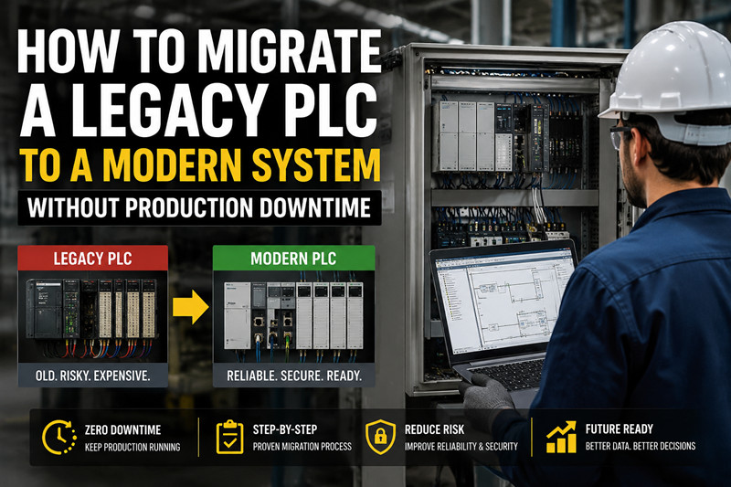
    How to Migrate a Legacy PLC to a Modern System Without Production Downtime Jun 09, 2026
    Hook You got the call. The PLC-5 in Bay 3 has started throwing intermittent processor faults, and the spares you stockpiled in 2019 are gone. Rockwell discontinued the 1771 I/O series in 2018. The technician who programmed this line retired three years ago, and the documentation lives in a binder with coffee stains on every page. Management wants the line running by Monday. This scenario plays out in factories across the Americas, Europe, and the Middle East every week. The installed base of legacy PLCs — PLC-5, SLC-500, S7-300, Modicon 984 — numbers in the millions. These systems still run critical processes. They're also ticking clocks. Migrating one without halting production is the single highest-stakes project most automation engineers will ever face. This guide walks through the full migration process — from audit to cutover — with the specific steps that keep your line running. The Basics   Why Migrate at All? If the system works, why touch it? Three reasons, and they get worse the longer you wait: First, parts availability. When Rockwell discontinued the PLC-5 platform, the secondary market absorbed demand — but by 2026, tested-working 1785-L80E processors cost $8,000 to $14,000 USD on eBay. That's more than a brand-new CompactLogix controller. Siemens S7-300 CPUs (315-2DP, 317-2DP) still trade actively on tztechio.com/siemens, but prices rise every quarter as supply dwindles. Second, cybersecurity liability. Legacy PLCs predate modern network security. No TLS, no role-based access control, no secure firmware updates. A PLC-5 connected to the plant network through an undocumented Ethernet bridge is a pivot point waiting to happen. Under NIS2 in the EU and similar frameworks emerging in Saudi Arabia and the UAE, plants face compliance deadlines that legacy hardware cannot meet. Third, integration friction. Your ERP wants production counts. Your MES wants cycle times. Your CMMS wants runtime hours. Getting these data points out of a PLC-5 means Modbus converters, OPC wrappers, and a support call to a system integrator who bills by the hour. A modern controller serves this data natively via MQTT or OPC UA. The Three Migration Strategies Rip and replace — Shut down, strip the panels, install everything new. Fastest engineering timeline. Most expensive in production loss. Only viable if you have a scheduled plant shutdown that's already long enough to absorb the work. Hot cutover — Run the old and new systems in parallel. Wire field devices to terminal blocks accessible by both systems. Validate the new PLC's logic against the old system's behavior, then switch over one I/O point at a time. Zero downtime. High engineering effort. This is the approach for continuous processes: chemical plants, water treatment, steel mills, anything that cannot stop. Phased migration — Convert one section of the process at a time. A packaging line with six machines migrates machine by machine. A wastewater plant migrates primary treatment first, secondary treatment next. Lower risk than rip-and-replace, lower engineering cost than hot cutover. Works well when the process has natural sub-sections. Choose based on two factors: the cost of one hour of downtime, and whether your process can physically stop without damaging equipment or product. The Real World   Step 1 — Audit Everything Before You Order Anything The most expensive mistake in PLC migration is ordering hardware based on the original drawings. Those drawings were wrong on commissioning day and have only gotten worse. Physically walk the panel. Photograph every card. Record part numbers and firmware revisions. Count spare slots. Map every wire from the field terminal to the I/O module terminal. This is tedious work, and it is non-negotiable. A single undocumented 4–20 mA loop wired to a spare channel that nobody remembered will ruin your cutover weekend. For a typical PLC-5 rack with 10 I/O cards, budget 8–12 hours for the physical audit. Use a tablet with a spreadsheet, not paper. Attach photos to each row. Notes like "TB3 terminal 14 — looks like a 24V signal, wire label says PSH-207, trace in P&ID drawing P-104" are worth their weight in gold six weeks later when you're commissioning. Step 2 — Map the Logic, Not Just the Tags The I/O list is the easy part. The logic translation is where projects go off the rails. PLC-5 programs use octal addressing and fixed data tables. S7-300 programs use absolute addressing with data blocks. Neither maps cleanly to a modern tag-based system. A rung that reads XIC I:012/03 BST XIO B3:0/5 NXB XIC N7:10/0 BND OTE O:015/07 needs to become something a maintenance electrician can still understand at 3 AM. The mapping process: · Extract the full program from the legacy processor using the original programming software (RSLogix 5, SIMATIC STEP 7, Modsoft). You need a Windows XP VM for most of this software. · Print the program as a PDF. Yes, paper — or at least a searchable PDF. You'll reference it hundreds of times. · Identify all data tables and their purpose. What is N7:0 through N7:50? Which are alarm bits? Which are recipe parameters? Which are intermediate calculations? · Build a cross-reference spreadsheet: old address → new tag name → new data type → any conversion needed. Plan for tag naming conventions that your maintenance team can navigate. · Translate the logic rung by rung. Automated translation tools exist (Rockwell's Migration Toolkit, Siemens' TIA Portal migration wizard) but budget at least 40% of the total program for manual verification and cleanup. Step 3 — The I/O Interface Strategy You have two options for connecting field wiring to the new system: Replace everything — Pull out the old chassis and I/O cards, install the new system, land all field wiring on new terminal blocks. Cleanest long-term solution. Requires every wire to be labeled, disconnected, and reconnected correctly. Budget 2–4 hours per I/O card for a two-person team. Use conversion hardware — Third-party adapters let you plug a modern controller into legacy I/O racks. ProSoft Technology, for example, makes EtherNet/IP-to-RIO adapters that let a CompactLogix control existing 1771 I/O. This saves weeks of rewiring. The trade-off: you're keeping 30-year-old I/O cards in service, and when one fails, you're back to searching the secondary market. For most projects, replace the I/O. The conversion hardware approach makes sense when you have hundreds of I/O points in explosion-proof areas where rewiring requires hot work permits, gas monitoring, and a shutdown anyway. But if the field wiring is accessible, bite the bullet and replace. Step 4 — HMI: Rewrite or Retain? Legacy HMIs — PanelView Standard, OP7/OP17, old Wonderware installations — rarely survive a migration intact. The communication drivers don't exist for the new controller. If the HMI screens are simple (alarm summary, trend, start/stop buttons), rewriting them in the new platform's native HMI environment takes 40–80 hours of engineering. This is usually the right call. If the HMI is complex (proprietary faceplates, extensive scripting, regulatory-validated screens for pharma/FDA applications), consider keeping the HMI and using a protocol gateway to bridge old to new. Kepware or Ignition can translate between the new controller's native protocol and whatever the old HMI expects. Regional Considerations In North America, most legacy systems are Allen-Bradley. The availability of retired technicians who know RSLogix 5 is better than anywhere else in the world — but they charge accordingly. If you're in Houston, Calgary, or Detroit, you can hire this expertise. If you're in Dammam or Dubai, plan for remote support. In Europe and the Middle East, Siemens S5 and S7-300/400 dominate the legacy base. The S5 was discontinued in 2006 but still runs chemical plants and power stations. Migrating S5 to S7-1500 or TIA Portal requires the original STEP 5 software and PG programming cables that haven't been manufactured in 15 years. Stock these cables before you start. Deep Dive   The Parallel Validation Method This is the technique that separates successful migrations from the ones that get written up as case studies in *Control Engineering* for the wrong reasons. Connect both the old and new PLCs to the field I/O through intermediate terminal blocks. Both systems read inputs simultaneously. Both systems execute their logic. But only the old system drives the outputs. Now run the process. Compare the internal state of both systems at every scan. Are the computed values identical? If an analog input reads 4.17 mA on the old system and 4.16 mA on the new, note the difference but don't panic — analog input modules have slight calibration variations. If the old system says a pump is running and the new system says it's stopped, find the discrepancy before you switch over. Rent or buy a protocol analyzer (Wireshark with the appropriate dissector works for most protocols) and capture both networks during a full production cycle. Build a script that compares the outputs the new system *would have written* against what the old system *actually wrote*. Any mismatch is a bug in your translation or an undocumented feature of the original program that you need to preserve. Expect this validation phase to take 1–2 weeks of parallel runtime for a continuous process. You're looking for rare edge cases — the alarm cascade that only triggers during a specific upset condition, the interlock that only activates when two valves are in specific positions simultaneously. The Cutover Moment Even with parallel validation, the cutover moment carries risk. Standard practice: schedule the cutover for the start of a maintenance window, not the end. If something goes wrong, you can revert to the old system and try again next window. The cutover sequence: 1. Confirm both systems are healthy and synchronized 2. Switch one non-critical output (a status light, an annunciator) to the new system 3. Verify correct behavior for 5 minutes 4. Switch one critical-but-redundant output (Pump A, while Pump B handles the load) 5. Verify correct behavior for 15 minutes 6. Switch all remaining outputs 7. Monitor for one full production cycle before declaring success Keep the old system powered and wired for at least one week after cutover. If production hits an issue at 2 AM on Tuesday, the ability to switch back in 30 seconds is worth the panel space. Documentation: The Part Everyone Skips After the migration succeeds, document: · The new I/O list with wire numbers and terminal designations · The tag database with descriptions · The program structure (tasks, programs, routines, and what each does) · The network architecture diagram · The cross-reference from old addresses to new tags · Commissioning test results · A troubleshooting guide written for the 3 AM maintenance call The next engineer who works on this system will not be you. They will not remember why FC42 handles the cascade control loop differently from every other PID block in the program. They will not know that output O:015/07 got renamed to PumpBay3_Start and why the alarm tag is Alarm_Bay3_PSH207_HiHi. Give them the documentation you wish you'd had when you started. Pricing & Availability · Engineering cost: $25,000–$80,000 USD for a mid-sized migration (200–500 I/O points), depending on logic complexity and HMI scope · Hardware cost: Varies by platform. CompactLogix-based migration (controller + chassis + I/O): $8,000–$20,000. S7-1500-based migration: $6,000–$18,000. Beckhoff-based migration: $4,000–$12,000 · Secondary market legacy parts: PLC-5 processors $8,000–$14,000; 1771 I/O modules $400–$2,000; S7-300 CPUs $1,200–$4,500. Available at tztechio.com/plc while supply lasts · Lead time: Most modern PLC hardware ships in 2–6 weeks in 2026. The constraint is usually engineering hours, not hardware availability FAQ How long does a typical PLC migration take? From audit to final handover, 8–16 weeks for a system with 200–500 I/O points. The physical cutover itself is 4–12 hours if well-planned. The bulk of the time is engineering: program translation, HMI rewrite, and testing. Can I migrate to a different brand? Yes, but the engineering effort roughly doubles. Brand-to-brand migration (PLC-5 to Siemens S7-1500, or S7-300 to CompactLogix) means no reuse of existing HMI screens, different I/O wiring conventions, and different programming paradigms. Worth it if you're standardizing your plant on a single brand, but budget accordingly. What if I can't find the original program? If the program is lost from the laptop but still running in the processor, most legacy PLCs allow upload. The uploaded program won't have comments or tag names — you get raw addresses with no documentation. This adds a heavy reverse-engineering phase. Budget an extra 3–6 weeks for a technician to figure out what each rung does by tracing field wiring and comparing against P&IDs. Do I need to update the control panel? At minimum, you need to mount the new PLC chassis and terminal blocks. If the panel is clean, has space, and the power supply can handle the new hardware's load, you might keep the enclosure. If the panel is 30 years old with degraded wire insulation and a previous tenant's undocumented modifications, replace it. A new stainless-steel enclosure costs $1,500–$4,000 and eliminates a future failure point. What about safety systems? If your legacy system handles safety functions (emergency stops, light curtains, gas detection), the migration must be reviewed against the current safety integrity level (SIL) requirements. A PLC-5 running safety logic under 1990s standards almost certainly does not meet IEC 61511 requirements today. Budget for a dedicated safety PLC (GuardLogix, Siemens F-CPU, Pilz PSS series) as part of the migration. See tztechio.com/industrial-automation for safety-rated PLCs currently in stock. Is there a migration grant or incentive program? Some regions offer energy-efficiency grants that cover automation upgrades. In the EU, the Horizon Europe program funds industrial digitalization projects. In Saudi Arabia, the National Industrial Development and Logistics Program (NIDLP) supports factory modernization. Check your local industrial development authority — the grant application takes work, but 20–40% cost coverage changes the ROI calculus. ----------------------------------------------------------------------------------------------------------------- TZ Tech is a professional supplier for industrial automation and electrical parts, as well as some instrumentation, telecommunication parts. We mostly sell the ready stock of distributor, with competitive price and short lead time. Even discontinued parts we may also can supply as we have a large inventory here.    We understand what you concern, so we will ensure the quality. We strictly screen the components you require, so you don’t need worry about any quality issues with the goods you receive. For specialized parts that have long since been discontinued, we will sincerely inform you the actual condition of the goods. All brand new parts we will support 1 year warranty.     If you need any related parts, please feel free to send an inquiry. Our staff will support quick response within 6 hours. (except weekend here)  
  • Beckhoff TwinCAT 3 Programming: A Practical Guide for Engineers Switching from Traditional PLCs
    Beckhoff TwinCAT 3 Programming: A Practical Guide for Engineers Switching from Traditional PLCs Jun 02, 2026
    Hook An engineer who spent ten years writing ladder logic on Allen Bradley and Siemens platforms opens TwinCAT 3 for the first time and freezes. The project tree sits inside Visual Studio. C++ files share space with PLC code. There are no chassis slots to configure, no hardware catalog to browse. The real-time kernel installs as a Windows driver alongside your web browser. This is Beckhoff TwinCAT 3 programming — a software-first approach to industrial control. The transition stings, but the payoff is a platform with capabilities no traditional PLC can match.   The Basics TwinCAT 3 (The Windows Control and Automation Technology) turns any Windows PC into a real-time PLC and motion controller. Unlike traditional platforms where the runtime lives on proprietary hardware, TwinCAT 3 isolates dedicated CPU cores from Windows via a real-time kernel driver — bare-metal scheduling, not virtualization. The engineering environment, TwinCAT 3 XAE, integrates into Microsoft Visual Studio as a shell extension. The PLC project lives inside a standard .sln solution. Source control works through Git. Multiple programmers can work simultaneously. For engineers accustomed to Studio 5000 or TIA Portal, the IDE feels like a software development environment — because it is one. The architecture breaks out of the IEC 61131-3 sandbox entirely. C++ and MATLAB/Simulink modules compile as native real-time tasks alongside PLC code, sharing memory directly through TcCOM (TwinCAT Component Object Model). The fieldbus is EtherCAT — Beckhoff's deterministic protocol that daisy-chains thousands of I/O terminals on a single cable with sub-millisecond cycle times. No PROFINET device naming, no GSDML files, no third-party drive configuration tools. The software stack: TwinCAT 3 XAE (engineering), TwinCAT 3 XAR (runtime execution), and the real-time kernel. Development is free. You can write, compile, and simulate full machine programs on an ordinary laptop with zero Beckhoff hardware.   The Real World A packaging integrator in Jeddah deployed a carton erector control system using a CX5130 embedded PC, EL1008 8-channel digital inputs, and EL2008 8-channel digital outputs. The entire project — install to cycling outputs — took one afternoon. Step 1 — Install TwinCAT 3 XAE. Download from Beckhoff's website. The installer drops a TwinCAT toolbar into Visual Studio and installs the real-time kernel driver. VS 2017, 2019, and 2022 shells are all supported. Step 2 — Create a project. File → New → Project → "TwinCAT Project." The solution contains a PLC node, SYSTEM node for real-time configuration, and an I/O node for EtherCAT devices. Target x86 for embedded PCs like the CX5130, x64 for newer IPCs. Step 3 — Choose programming language. Right-click the PLC node, add a PLC project. Beckhoff defaults to Structured Text (ST), and most programmers migrate there because ST handles arrays, state machines, and complex logic far more cleanly than ladder. That said, Continuous Function Chart (CFC) — a free-form graphical language where you place blocks on a canvas and draw signal wires — is uniquely suited to process control loops. Ladder Logic (LD) remains available for discrete interlocks that maintenance teams need to troubleshoot. For the carton erector, the engineer wrote a state machine in ST with states for Home, Feed, Fold, Glue, and Eject. Each state assigned outputs to the EL2008 and read inputs from the EL1008. Step 4 — Scan EtherCAT devices. Right-click "Devices" in the I/O tree, select "Scan." TwinCAT 3 discovers every connected terminal, drive, and I/O slice automatically. EL1008 appears as an 8-channel input terminal. EL2008 appears as an 8-channel output. Link terminal channels to PLC variables by dragging them into your variable declaration. Step 5 — Activate configuration. Click "Activate Configuration" in the toolbar. TwinCAT 3 compiles the PLC code, builds the real-time config, and loads everything onto the runtime. Press "Login," select "Run Mode," and the CX5130 runs PLC logic at the configured cycle time — typically 1 ms. The only hiccup: the laptop couldn't reach the CX5130 because the AMS NetID wasn't routed. Adding the laptop's NetID via the TwinCAT router tool (taskbar icon) resolved it in under two minutes.   Deep Dive C++ Integration and TcCOM The feature that separates TwinCAT 3 from every traditional PLC platform: native C++. You add a C++ module directly to the real-time project, write standard C++ with real-time extensions, and it runs as a TcCOM object on the same isolated core as the PLC — sharing memory through pointers with zero latency overhead. A German packaging OEM used this to run an OpenCV-based bottle cap inspection at 400 ppm. The C++ vision module exchanges pass/fail results with the PLC state machine via a shared struct. A traditional approach — external IPC over OPC UA — would add 10-50 ms of latency and an entire extra network link to maintain. MATLAB/Simulink Integration The TE1400 target exports Simulink models as TcCOM modules. A process engineer designs a PID cascade, clicks "Generate Code," and the model compiles to a real-time object in the TwinCAT 3 project. The PLC programmer maps model inputs and outputs to real I/O terminals. A UAE water treatment plant used this for a coagulation dosing algorithm — turbidity and pH sensors wired to EL3024 analog inputs, model output driving EL4024 analog outputs to dosing pumps. Total integration: one day. Motion Control NC PTP handles standard point-to-point positioning with trapezoidal or S-curve profiles — conveyors, linear actuators, rotary positioning. TwinCAT CNC is a full numerical control kernel supporting G-code, 5-axis kinematics, tool radius compensation, and look-ahead. An Italian CNC shop runs 5-axis machining on TwinCAT CNC with AX5000 servo drives at 0.1 ms interpolation cycles. TwinCAT HMI TwinCAT HMI (TE2000) serves HTML5/JavaScript dashboards from the Beckhoff IPC. Any browser-equipped device — panel PC, tablet, smartphone — displays the same screens. Communication between the HMI server and PLC uses ADS over the local AMS router with sub-millisecond latency. No proprietary panel hardware required. Multi-Core Task Assignment TwinCAT 3 pins individual tasks to specific isolated cores with preemption disabled. A typical quad-core CX2040 layout: Core 1 runs the PLC state machine at 1 ms, Core 2 runs NC PTP at 0.5 ms, Core 3 runs a C++ vision module at 5 ms, and Core 0 handles Windows. If any real-time task exceeds its cycle, TwinCAT reports a violation and enters a configurable error state. For high-speed packaging or CNC interpolators, manual core isolation eliminates jitter that would destabilize the machine.   Pricing and Availability TwinCAT 3 licenses are one-time purchases per target device. TC1200 (PLC-only, IEC 61131-3) is approximately $700 for a CX5130. TC1250 adds NC PTP motion. TC1300 unlocks C++. The full suite on a CX2040 runs $3,000-$4,000. The engineering environment is free for development and simulation. Embedded PCs: CX7000 (~$400 entry-level), CX2000 series ($1,500-$4,000), C6030 ultra-compact IPC ($2,000+). I/O terminals like EL1008 and EL2008 run $80-$120 per module. Standard catalog lead times run 1-3 weeks. Browse Beckhoff embedded PCs, EtherCAT terminals, and licensing and PLC solutions at tztechio.com. FAQ Q: Can I run TwinCAT 3 on a regular laptop for development? Yes. TwinCAT 3 XAE installs on any Windows 10/11 x64 machine. The real-time kernel runs in local mode using isolated CPU scheduling. You can write, compile, and simulate full PLC, C++, and motion programs without Beckhoff hardware. For I/O simulation, write a short ST routine generating sensor feedback. For motion, enable axis simulation mode in SYSTEM configuration. Q: Is TwinCAT 3 harder to learn than Studio 5000 or TIA Portal? The Visual Studio environment adds a learning curve if you've only used dedicated PLC IDEs. But the I/O scanning workflow is simpler than TIA Portal's hardware catalog, and engineers familiar with structured text and basic software practices (version control, debugging, variable scoping) typically find TwinCAT 3 intuitive within the first week. Beckhoff's F1 help is thorough and context-aware. Q: Do I need a Beckhoff IPC, or can I use a third-party PC? The runtime works on any x86 Windows PC, but Beckhoff validates real-time behavior only on its own hardware. Third-party PCs risk jitter from chipset, BIOS power management, or driver issues. Develop and simulate on any laptop. For production, use Beckhoff IPCs — the cost difference is negligible compared to debugging non-validated hardware. Q: Can I mix ladder logic and structured text in the same project? Yes. A single PLC project can contain PRGs, FBs, and FCs in any combination of ST, LD, FBD, and CFC. A ladder routine can call an ST function block. A CFC diagram can reference ladder networks. Compilation and linking are language-agnostic. Q: Does TwinCAT 3 support OPC UA and MQTT for Industry 4.0? Yes. TF6100 provides OPC UA server functionality exposing PLC symbols as configurable nodes. TF6701 adds MQTT publish/subscribe. Both run as TcCOM modules on the real-time side, independent of Windows services. Q: How are firmware and software updates handled on a running machine? TwinCAT 3 supports online changes — modify PLC code, add variables, adjust task config while the runtime stays in Run mode. Structural changes (new EtherCAT devices, cycle time modifications, C++ modules) require an "Activate Configuration" with a brief controlled restart. For 24/7 processes, redundant TwinCAT configurations with automatic failover are available.    
  • PLC Troubleshooting: 10 Common Faults and How to Fix Them
    PLC Troubleshooting: 10 Common Faults and How to Fix Them May 28, 2026
    Introduction PLCs are engineered for reliability. When one fails, the impact on production is immediate and expensive. Yet the majority of PLC faults stem from a handful of recurring causes—most of which a qualified technician can diagnose and resolve without replacing the controller. This guide covers the ten most common PLC problems encountered in industrial environments, with practical troubleshooting steps you can apply today. 1. PLC Communication Failure Symptoms: PLC stops responding to HMI, programming computer cannot go online, network devices disappear from the bus. Common causes: · Loose or damaged Ethernet cable · Incorrect IP address configuration · Duplex mismatch on network switches · Driver failure on the PLC port Troubleshooting steps: 1. Check physical cable connections at both PLC and switch 2. Verify IP address matches the project configuration (ping test) 3. Ensure network switch port settings match PLC (auto-negotiate vs. fixed speed) 4. Reboot the PLC and switch 5. If using RS-232/RS-485 serial, verify baud rate and parity settings 2. Digital Input Not Reading Symptoms: Input LED on the module is off when the sensor is active, or input stays permanently on. Common causes: · Incorrect voltage level (24V DC vs. 110V AC mixed up) · Failed input module · Wiring error or loose terminal · Sensor power supply issue Troubleshooting steps: 6. Measure actual voltage at the input terminal with a multimeter 7. Verify sensor is powered (check LED indicators on proximity sensors) 8. Swap the input module with a known-working module to rule out hardware failure 9. Check that the sensor type (PNP vs. NPN for DC sensors) matches the module configuration 3. Analog Input Fluctuation or Noise Symptoms: Analog input value jumps erratically, shows unrealistic negative values, or drifts over time. Common causes: · Electromagnetic interference (EMI) from nearby VFDs or motors · Ground loop issues · Signal wire run alongside power cables · 4-20mA loop power problem Troubleshooting steps: 10. Separate signal cables from power cables by at least 6 inches 11. Use shielded twisted-pair cable for analog signals 12. Verify 24V DC supply to the transmitter is stable 13. Check that the analog module's signal type (0-10V, 4-20mA) matches the sensor 14. Add a filter value in the PLC program to dampen noise (most PLC software allows input filtering) 4. PLC Scan Time Too Long Symptoms: Outputs update with noticeable delay, machine response feels sluggish, timers seem inaccurate. Common causes: · Program grown too large without optimization · Excessive communication traffic on the network · Too many expensive instructions (complex PID loops, trigonometry) · Analog input filtering set too high Troubleshooting steps: 15. Most PLC software includes a scan time monitor—check it first 16. Move communication instructions outside the main program scan (use periodic tasks) 17. Reduce the number of messages on EtherNet/IP or PROFINET 18. Simplify or split large subroutines 19. Consider a faster CPU if scan time exceeds 20ms on time-critical applications 5. Output Module Fails to Energize Load Symptoms: Output LED lights but load does not activate. Common causes: · Blown fuse on the output module · Overload condition triggered thermal protection · Wiring error (common line not connected) · Failed semiconductor output (for solid-state modules) Troubleshooting steps: 20. Check fuse status on the module (most modules have visible fuse indicators) 21. Measure voltage across the output terminal while commanding it on 22. Verify the load is not open-circuited (disconnect and measure resistance) 23. For relay outputs, listen for the relay click—if silent, coil is dead 24. Check that the output type (sourcing vs. sinking) matches your load wiring 6. PLC Memory Full or Program Won't Download Symptoms: Download fails with memory error, new instructions cannot be added, firmware update rejected. Common causes: · Program code or data tables grown beyond CPU memory capacity · Accumulated trend logs, recipe data, or historical data consuming memory 25. Corrupt project file Troubleshooting steps: 26. Open the program in the development environment and check memory usage 27. Clear trend logs, historical data, and non-essential recipe files from the CPU 28. Archive the current project and compare file sizes—bloat indicates recoverable data 29. If firmware update is needed, back up the project first, then update firmware, then reload 30. As a last resort, factory reset and reload from a clean backup 7. PLC Keeps Entering Fault Mode Symptoms: Controller shows fault indicator, program stops, fault code displayed on CPU or HMI. Common causes: · Program logic error causing an unlatched fault · Hardware failure (CPU, module, or power supply) · Power supply voltage dropout during operation · I/O mismatch between program and actual hardware Troubleshooting steps: 31. Record the fault code immediately—look it up in the manufacturer's documentation 32. Common fault codes indicate: output overload (F49 on Allen Bradley), I/O config mismatch (016h on Siemens), Watchdog timeout 33. Check the event log in the programming software for preceding events 34. Is the fault latched or unlatched? Unlatched faults often indicate a program logic issue rather than hardware failure 35. Restore from a known-good backup if the fault persists and no cause is found 8. Battery Backup Failure Symptoms: PLC loses program on power loss, retained values reset to defaults, battery low indicator lights. Common causes: · Battery reached end of life (typically 2-5 years) · Battery not installed correctly · Battery voltage drained by high memory retention load Troubleshooting steps: 36. Replace battery with manufacturer-specified type while PLC is powered—never let the CPU go unpowered with a dead battery 37. After replacement, verify retained tags and program are intact 38. If values still lost, the battery may have failed during replacement window—improve changeover procedure 39. Consider using闪存 (flash memory) retention as primary backup for new installations instead of battery 9. VFD Communication Not Working with PLC Symptoms: VFD runs but ignores speed commands, fault code on VFD, PLC shows communication timeout error. Common causes: · Incorrect network address (Node ID or IP address mismatch) · Parameter settings on VFD blocking network control · Using wrong profile (Allen Bradley VFDs need parameter 90 set correctly for EtherNet/IP) · Cable or switch issue on the network segment Troubleshooting steps: 40. Verify VFD network address matches PLC configuration (check in RSLogix or TIA Portal) 41. Confirm VFD parameters allow network control (Drive Parameters → Network Control → Enabled) 42. For EtherNet/IP, verify the assembly instance numbers in the PLC's I/O configuration match the VFD 43. Ping the VFD from the programming computer to confirm network connectivity 44. Check that the VFD's control source is set to "Network" rather than "Keypad" or "Terminal" 10. Ground Loop and Electrical Noise Issues Symptoms: Intermittent faults, random input triggering, unexplained program behavior, communication errors during motor startup. Common causes: · Inconsistent grounding between PLC, field devices, and power distribution · Ground loops formed when devices share multiple ground paths · No dedicated signal ground wire in cable runs · PLC cabinet not properly bonded to building ground Troubleshooting steps: 45. Measure ground resistance between PLC cabinet and building ground—should be less than 1 ohm 46. Use isolated DC power supplies for field devices to break ground loops 47. Ensure all signal commons connect to a single point ground 48. Install ferrite beads on communication cables near PLC to suppress high-frequency noise 49. Route signal cables in dedicated trays, never alongside motor power cables Conclusion PLC faults rarely come out of nowhere. Most problems fall into a handful of categories—power issues, communication breakdowns, wiring errors, and noise interference. A systematic approach, a multimeter, and understanding of the specific platform's diagnostic tools will resolve the majority of issues without part replacement. Document every fault, the symptoms observed, and the resolution. Build an internal knowledge base. This is the fastest path to reducing mean time to repair across your facility. Frequently Asked Questions Q: Should I always replace a faulty PLC module? A: Not necessarily. Many module "failures" are wiring, configuration, or power issues. Always troubleshoot before replacing. Modules can sometimes be repaired by the manufacturer or third-party service providers. Q: How often should I backup PLC programs? A: Every time a program change is made. Additionally, perform quarterly archival backups stored in a separate location. Label backups with date, program version, and machine ID. Q: Can a PLC be damaged by voltage spikes? A: Yes. Transient voltage suppressor (TVS) diodes and proper grounding are the first line of defense. Install surge protection on power feeds and communication lines. Regular power conditioning pays for itself quickly in industrial environments. Q: What is the typical lifespan of a PLC? A: With proper environment and maintenance, PLCs routinely operate 15-20 years. CPU modules and I/O cards may require component-level replacement as electrolytic capacitors age. Q: Should I keep spare PLC modules on hand? A: For critical machines, yes. Keep at minimum one spare CPU, one spare power supply, and key I/O modules. For non-critical applications, establish a service agreement with your distributor for 24-48 hour replacement. Related Products · Allen Bradley PLCs — ControlLogix, CompactLogix, MicroLogix · Siemens PLCs — S7-1500, S7-1200 · PLC I/O Modules — Digital and analog input/output modules · VFDs — Variable frequency drives for motor control
  • Industrial Sensor Types & Selection: Proximity, Photoelectric, Pressure & More
    Industrial Sensor Types & Selection: Proximity, Photoelectric, Pressure & More May 27, 2026
    Introduction Sensors are the eyes and ears of industrial automation. Without sensors, a PLC cannot know whether a product is in position, if a tank is full, or if a motor is overheating. Choosing the right sensor for each application is critical: the wrong sensor leads to production downtime, false triggers, or safety hazards. This guide covers the most common industrial sensor types — proximity sensors, photoelectric sensors, pressure sensors, and temperature sensors — their working principles, key specifications, and a brand comparison of Bently Nevada, Honeywell, Pepperl+Fuchs, and Keyence. Proximity Sensors Proximity sensors detect the presence or absence of an object without physical contact. They are the workhorse of factory automation, used for position detection, counting, and process control. Inductive Proximity Sensors Inductive sensors detect metal objects by generating an electromagnetic field. When a metal target enters the field, eddy currents reduce the oscillation amplitude, triggering a switch output. Key specifications: · Sensing distance: 0.8mm - 50mm (varies by target size and sensor model) · Target: Ferrous and non-ferrous metals (steel, aluminum, brass) · Output: PNP (sourcing) or NPN (sinking), NO or NC · Protection: IP67 standard, IP69K for pressure wash Capacitive Proximity Sensors Capacitive sensors detect both metallic and non-metallic targets (plastics, liquids, granules) by measuring changes in capacitance between the sensor electrode and the target. Key specifications: · Sensing distance: 1mm - 40mm · Target: Metals, plastics, wood, paper, glass, liquids · Can detect levels inside non-metallic containers · More sensitive to environmental factors (humidity, dust) Magnetic Proximity Sensors (Reed Switch / Hall Effect) · Reed switches: Contact-based, activated by permanent magnet. Simple and inexpensive. · Hall effect sensors: Solid-state, detect magnetic field changes. No contact wear, longer life. Photoelectric Sensors Photoelectric sensors use a light beam (typically infrared or red LED) to detect objects. They offer longer sensing distances than inductive/capacitive sensors and can detect transparent objects, labels, and color differences. Diffuse (Self-Contained) Photoelectric Sensors Emitter and receiver in one housing. Light is reflected off the target back to the receiver. Range: 50mm - 3m. Best for: detecting presence of any object in close range. Retroreflective Photoelectric Sensors Emitter and receiver in one housing. Reflector placed opposite. Object blocks the reflected beam. Range: up to 15m. Best for: long-range detection, detecting clear/transparent objects. Through-Beam Photoelectric Sensors Emitter and receiver are separate units. Object breaks the beam. Range: up to 60m. Best for: maximum accuracy, counting, detecting small objects. Background Suppression (BGS) Sensors Advanced diffuse sensors with built-in distance measurement. Ignores background objects. Best for: detecting objects against a conveyor or machine frame. Key specifications: · Light source: Red LED (visible), Infrared LED, Laser (precision) · Response time: 0.1ms - 50ms (laser: <0.1ms) · Output: PNP/NPN, Digital or Analog · Protection: IP67 / IP69K for food industry Pressure Sensors Pressure sensors measure the force per unit area exerted by a fluid (liquid or gas). They are essential for hydraulic systems, pneumatic controls, process monitoring, and safety systems. Types of Pressure Measurement · Gauge pressure: Relative to atmospheric pressure (0 bar = atmospheric). Most common. · Absolute pressure: Relative to perfect vacuum. Used for barometric measurement. · Differential pressure: Difference between two pressure points. Used for filter monitoring, flow measurement. · Sealed gauge: Pre-set reference at 1 atm (sea level). Used in aircraft and aerospace. Pressure Sensor Technologies · Strain gauge / Piezoresistive: Metal diaphragm with bonded strain gauge. Good for high pressure (up to 1000 bar). · Thin-film: Strain gauge integrated onto diaphragm. Excellent long-term stability. Most common for industrial use. · Capacitive: Ceramic or metal diaphragm changes capacitance. Excellent for low pressure and vacuum. · Piezoelectric: Generates charge when stressed. For dynamic pressure measurement (hydraulic hammer, pulsating systems). Key specifications: · Pressure range: 0-1 bar to 0-1000 bar (gauge or absolute) · Output: 4-20mA (current loop, industry standard), 0-10V, IO-Link · Accuracy: ±0.25% to ±0.05% of full scale · Process connection: G1/4, G1/2, NPT, flange Temperature Sensors RTD (Resistance Temperature Detector) Uses platinum resistance (typically Pt100). Accuracy: ±0.1°C to ±0.5°C. Range: -200°C to +600°C. Best for: precision measurement, wide temperature range. Thermocouple Two dissimilar metals joined at a junction. Generates voltage proportional to temperature. Range: -270°C to +2300°C. Best for: extremely high temperatures, fast response. Thermistor Semiconductor material with temperature-dependent resistance. Range: -100°C to +300°C. Best for: low-cost, high sensitivity applications. Infrared (Non-Contact) Temperature Sensors Measures emitted infrared radiation. Range: -40°C to +3000°C. Best for: moving objects, hazardous areas, inaccessible measurement points. Sensor Brand Comparison Feature Bently Nevada Honeywell Pepperl+Fuchs Keyence Specialty Vibration & machinery monitoring Pressure, temperature, flow Inductive, photoelectric, vision Photoelectric, vision, laser Key Product 3300 XL 8mm Proximitor PX2 Series pressure sensors NJ series vision sensors IV3 series vision sensors Strength Oil & gas turbine monitoring Aerospace & industrial process Intrinsically safe sensors High-speed inspection Price Level $$$ (premium) $$-$$$ $$ $$-$$$ Best For Turbines, compressors, pumps Process automation Factory automation Quality inspection Global Support Excellent (Baker Hughes) Excellent Good Good   · Bently Nevada (Baker Hughes): The gold standard for vibration and machinery protection in oil & gas, power generation, and heavy industry. The 3300 XL series is the most deployed proximity sensor in rotating equipment worldwide. · Honeywell: Broad portfolio covering pressure, temperature, flow, and force. PX2 series pressure sensors are industry standard for hydraulic systems. Excellent for process automation and building management. · Pepperl+Fuchs: Germany's sensor specialist. World leader in intrinsically safe and explosion-proof sensors for chemical, pharmaceutical, and oil & gas. Exceptional build quality for factory automation. · Keyence: Japan's inspection technology leader. Best-in-class vision sensors and laser profile meters. IV3 series delivers high-speed, accurate inspection for packaging and electronics assembly. Sensor Selection: 5 Key Parameters 1. Sensing Distance & Target Material Inductive sensors only detect metals (use capacitive or photoelectric for non-metals). Measure the actual gap — use sensors with 1.5-2× the required sensing distance for margin. 2. Output Type PNP (sourcing) is standard in Europe and Asia. NPN (sinking) is common in Japan and Allen Bradley systems. Check your PLC input card compatibility. Consider analog output (4-20mA, 0-10V) for process monitoring. 3. Environmental Conditions IP67/IP69K rating for washdown. Explosion-proof (ATEX/IECEx) for hazardous areas. Temperature extremes require sensors rated beyond operating range. Chemical exposure requires compatible wetted materials. 4. Response Time High-speed counting or rapid part detection (<1ms): Use laser photoelectric or Hall effect sensors. Standard detection (10-50ms): LED photoelectric or inductive sensors. 5. Communication Protocol Traditional: Discrete I/O (PNP/NPN). Modern: IO-Link (easy configuration, diagnostic data), PROFINET, EtherNet/IP. Choose sensors compatible with your PLC ecosystem. Conclusion Selecting the right sensor requires matching the detection principle to the target material, environment, and performance requirements. For rotating equipment protection, Bently Nevada is the undisputed leader. For process automation and pressure measurement, Honeywell offers the broadest portfolio. Pepperl+Fuchs excels in hazardous-area sensors. Keyence dominates in high-speed inspection and vision-based quality control. Frequently Asked Questions Q: What is the difference between PNP and NPN sensors? A: PNP sensors source current (current flows from sensor to load). NPN sensors sink current (current flows from load to sensor). Choose based on your PLC input card type: PNP input cards require PNP sensors, NPN input cards require NPN sensors. Q: Can inductive sensors detect non-metallic objects? A: No. Inductive sensors only detect conductive or ferromagnetic metals. For non-metals (plastics, wood, liquids), use capacitive sensors, photoelectric sensors, or ultrasonic sensors. Q: What does IP67 mean? A: IP (Ingress Protection) rating: First digit = solid particle protection (6 = dust-tight). Second digit = liquid protection (7 = immersion up to 1m for 30 minutes). IP69K adds high-pressure, high-temperature washdown protection. Q: What is IO-Link? A: IO-Link is a standardized point-to-point communication protocol (IEC 61131-9) for smart sensors. It enables remote configuration, diagnostic data readout, and easy sensor replacement without re-wiring. Increasingly standard in modern automation. Q: How do I choose between a proximity sensor and a photoelectric sensor? A: Use proximity sensors when: target is metal, short sensing distance (<50mm), dirty environment, high switching frequency. Use photoelectric sensors when: non-metallic target, longer distance required, transparent object detection, color discrimination needed. Related Products · Bently Nevada 3300 XL 8mm Proximitor Sensor ·   Industry-standard vibration sensor for rotating equipment protection. 8mm sensing distance, IP67, -40°C to +180°C operating range. · Honeywell PX2 Series Pressure Transducer ·   Heavy-duty pressure sensor for hydraulic systems. 0-250 bar range, 4-20mA output, IP67, G1/2 process connection. · Pepperl+Fuchs NBB10-30GM50-E2 Inductive Sensor ·   Standard inductive proximity sensor. 10mm sensing distance, PNP NO output, IP67, M30 threaded body. · Keyence IV3 Series Vision Sensor ·   High-speed vision inspection sensor for quality control. Detects presence, color, shape, and dimensions at 1000 inspections/sec. · Pepperl+Fuchs  Capacitive level sensor for detecting liquids and granules in tanks and hoppers. Adjustable sensitivity, IP68 rated. ------------------------------------------------------------------------------------------------------------------------- TZ Tech is a professional supplier for industrial automation and electrical parts, as well as some instrumentation, telecommunication parts. We mostly sell the ready stock of distributor, with competitive price and short lead time. Even discontinued parts we may also can supply as we have a large inventory here.    We understand what you concern, so we will ensure the quality. We strictly screen the components you require, so you don’t need worry about any quality issues with the goods you receive. For specialized parts that have long since been discontinued, we will sincerely inform you the actual condition of the goods. All brand new parts we will support 1 year warranty.     If you need any related parts, please feel free to send an inquiry. Our staff will support quick response within 6 hours. (except weekend here)
  • PLC Beginner's Complete Guide: What is a PLC and How to Choose One
    PLC Beginner's Complete Guide: What is a PLC and How to Choose One May 25, 2026
    Meta Title: VFD Basics & Selection Guide: How to Choose a Variable Frequency Drive (2026)Meta Description: Complete VFD guide covering how variable frequency drives work, why use a VFD, key selection parameters, and brand comparison of Mitsubishi FR-E800, Danfoss FC101, Schneider ATV320.   Introduction Variable Frequency Drives (VFDs) — also called Variable Speed Drives (VSDs) or Inverters — are among the most widely used components in industrial automation. A VFD controls the speed of an AC electric motor by varying the frequency and voltage of the power supply. The result: energy savings of 20-50%, improved process control, and extended motor lifespan. This guide covers VFD working principles, when and why to use them, key selection parameters, and a practical comparison of leading VFD brands: Mitsubishi FR-E800, Danfoss FC101, Schneider Altivar 320, and ABB ACS580. What is a Variable Frequency Drive? A VFD is an electronic power converter that takes fixed-frequency AC input (50/60Hz) and converts it to adjustable-frequency, adjustable-voltage output. By controlling the output frequency, you directly control motor speed: Motor Speed (RPM) = 120 × Frequency (Hz) / Number of Poles For a 4-pole motor connected to a 60Hz supply: Full speed = 1800 RPM. With VFD set to 30Hz: Motor speed = 900 RPM. This relationship makes VFDs indispensable for fans, pumps, conveyors, compressors, and any application where variable speed saves energy. Why Use a VFD? 5 Key Benefits Energy Savings Reducing motor speed by 20% saves approximately 50% energy (power follows the cube of speed). For a 50HP fan running at 80% speed, annual savings can exceed $5,000. Soft Start / Reduced Inrush Current VFDs ramp up voltage and frequency gradually, eliminating the 6-8× locked rotor current surge during direct-on-line starting. This protects motors and reduces mechanical stress. Process Control & Precision Variable speed control enables smooth acceleration/deceleration, precise speed regulation (±0.5%), and synchronized multi-axis motion. Critical for packaging lines, CNC machines, and mixing. Reduced Mechanical Wear Soft starts and controlled stops reduce belt wear, gearbox stress, and bearing load. Maintenance intervals extend by 2-3× on average. PLC / Automation Integration Modern VFDs support EtherNet/IP, PROFINET, Modbus RTU/TCP, CANopen for seamless PLC integration and SCADA remote monitoring. How Does a VFD Work? A VFD consists of three main stages: Rectifier Stage AC input is converted to DC using a diode bridge rectifier. This creates harmonic distortion (THD ~30-40%). DC Bus / Filtering DC voltage is smoothed by capacitors and inductors. The DC bus stores energy to handle momentary power interruptions and motor regeneration. Inverter Stage IGBTs switch at high frequency (2-16kHz) to create a pseudo-sine-wave AC output at the desired frequency. This is Pulse Width Modulation (PWM). Key VFD control methods: · V/F Control: Standard for constant torque loads · Vector Control: Better low-speed torque and regulation · Sensorless Vector: Motor flux estimation without encoder · Closed-loop Vector (with encoder): ±0.01% speed accuracy VFD Selection: 6 Key Parameters 1. Power Rating (kW / HP) Match the VFD power to the motor nameplate current and voltage. Choose a VFD rated at least equal to — preferably 10-20% above — the motor FLA (Full Load Amps). Undersizing causes overheating. 2. Input Voltage & Phase Common ratings: 200-240V single-phase (small VFDs), 380-480V three-phase (industrial standard), 500-690V (high-power). Never connect a single-phase VFD to a three-phase motor. 3. Load Type Constant Torque (conveyors, compressors): Requires high starting torque. Variable Torque (fans, pumps): Maximum energy savings. Match VFD to load profile. 4. Communication Protocol Match your PLC ecosystem: EtherNet/IP (Allen Bradley), PROFINET (Siemens/Schneider), Modbus RTU (universal). For motion: CANopen or EtherCAT. 5. Environmental Protection IP20 (inside cabinet). IP54/55 (dusty/humid). IP66 (outdoor/washdown). High ambient temps (>40°C) require derating or enclosure cooling. 6. Braking / Regeneration For frequent braking or overhauling loads (cranes, conveyors), add a braking resistor. Otherwise DC bus voltage rises and triggers overvoltage fault. VFD Brand Comparison Feature Mitsubishi FR-E800 Danfoss FC101 Schneider ATV320 ABB ACS580 Power Range 0.1-630kW 0.12-75kW 0.18-30kW 0.75-250kW Voltage 200-240V / 380-480V 200-240V / 380-480V 200-240V / 380-480V 380-480V Communication Built-in Ethernet Modbus RTU, fieldbus Modbus RTU, CANopen, Profinet Built-in Modbus RTU Programming FR Configurator 2 MCT 10 / built-in display SoMove / Display DriveComposer Pro Key Strength Ethernet & motion control HVAC/pump optimization Compact, easy commissioning Industrial robustness   · Mitsubishi FR-E800: Best for machines requiring built-in Ethernet (CC-Link IE Field, Modbus TCP) and high-speed motion. Excellent encoder feedback support. · Danfoss FC101: Purpose-built for HVAC and water treatment. Exceptional vCurve optimization for pumps and fans. Competitive price for 0.75-75kW range. · Schneider Altivar 320: Compact and easy to set up via SoMove or built-in display. Good for simple pump/fan/conveyor applications. · ABB ACS580: Industrial-grade, reliable from the ABB ACS880 platform. Excellent for heavy industrial loads. Strong global service network. Conclusion Selecting the right VFD comes down to matching power rating, voltage, communication protocol, and load type with your application. Mitsubishi FR-E800 leads in connectivity and motion control. Danfoss FC101 is optimized for HVAC and pump applications. Schneider ATV320 offers simplicity and compactness. ABB ACS580 brings industrial robustness. Frequently Asked Questions Q: What is the difference between a VFD and a soft starter? A: A soft starter only controls voltage during start/stop. It cannot vary motor speed. A VFD controls both frequency and voltage continuously, enabling variable speed and energy savings throughout the process. Q: Can a VFD damage a motor? A: If properly sized and configured, a VFD extends motor life. Main risks: (1) overheating from low-speed operation, (2) voltage spikes from long motor cables. Use output filters for cable runs >50m. Q: How much energy can a VFD save? A: For variable-torque loads (fans, pumps), reducing speed by 20% saves ~50% energy. A 50HP fan at 75% speed for 8,000 hours/year can save $8,000-$12,000/year. Payback: 1-3 years. Q: Do VFDs cause harmonic distortion? A: Yes. Standard 6-pulse VFD rectifiers create THDi ~30-40%. Use input reactors, active front end (AFE) drives, or multi-pulse (12/18-pulse) VFDs to reduce below 5% THDi. Q: Can I run a motor at 90Hz via VFD? A: Standard motors are rated for 50/60Hz. Running at 90Hz requires a VFD-rated motor (class F/H insulation, balanced bearings). Consult manufacturer before exceeding nameplate frequency by >20%. Related Products · Mitsubishi FR-E800 VFD ·   High-performance VFD with built-in Ethernet and advanced motion functions. 0.1-630kW range. · Danfoss FC101 VFD ·   HVAC and pump optimized VFD with intuitive commissioning. 0.12-75kW. · Schneider Altivar 320 ·   Compact VFD for simple to medium complexity applications. 0.18-30kW. · ABB ACS580 VFD ·   General purpose industrial VFD with robust build quality. 0.75-250kW. · VFD Input Reactor (Harmonic Filter) ·   Reduces harmonic distortion from VFD rectifiers. Essential for plants with sensitive equipment.
  • How PLCs Run Water Treatment Plants in the Middle East and Europe: 2026 Automation Guide
    How PLCs Run Water Treatment Plants in the Middle East and Europe: 2026 Automation Guide May 20, 2026
      URL Slug: plc-water-treatment-automation-middle-east-europe-2026 The Invisible Infrastructure PLC in water treatment plants automation Middle East Europe 2026 — search this and you get vendor pages, academic papers, and a few outdated white papers. What you do not get is a straight answer from someone who has actually specified the hardware for a working plant. This article fixes that. It covers how PLCs actually run water and wastewater treatment facilities: which platforms are deployed, what they control, how they integrate with SCADA, and what the regulatory landscape looks like in 2026 for both regions. The reason this matters: water treatment is one of the most demanding PLC applications because it combines continuous process control, safety-critical chemical dosing, harsh environments (corrosive atmospheres, humidity), and regulatory reporting requirements that make SCADA integration non-negotiable. A PLC failure in a water treatment plant is not an inconvenience — it can be a public health event.   What PLCs Control in Water Treatment Plants A modern municipal or industrial water treatment plant automates four core processes: chemical dosing, aeration, filtration, and backwash cycles. PLCs also handle auxiliary functions like pumping, level control, and flow balancing. The complexity varies significantly between a small package plant (a few thousand gallons per day) and a large metropolitan treatment facility (hundreds of millions of gallons per day). Chemical Dosing Chemical dosing is the most safety-critical function. Chlorine (or chloramine) dosing prevents pathogen breakthrough. Coagulants (aluminum sulfate, ferric chloride) aggregate suspended solids. pH adjustment chemicals (lime, sulfuric acid) correct alkalinity. Phosphorus removal chemicals (ferric chloride, alum) target nutrient loads. The PLC controls dosing pumps in response to online analyzer readings. A typical configuration: · Flow transmitter on the inlet header (measures flow rate, GPM) · Residual chlorine analyzer downstream of the contact tank · PLC calculates the required dose rate (mg/L) based on flow-proportional dosing · Analog output (4–20mA) drives the dosing pump stroke or speed Siemens S7-1500 systems handle this well in UAE municipal projects — the built-in PID control functions (PID_Compact, PID_3Step) are well-suited for dosing loops, and the TIA Portal libraries include pre-built water treatment function blocks that reduce programming time. Allen Bradley ControlLogix with 1756-IF8 analog inputs and 1756-OF4 analog outputs handles the same function in US plants — the RSLogix and Studio 5000 environment is familiar to US water utilities, and the Allen Bradley platform has deep integration with Rockwell Automation PlantPAx process automation system. Aeration Control Aeration serves two purposes: biological oxidation of organic matter (BOD removal) and maintaining dissolved oxygen (DO) levels for nitrification. In activated sludge processes, the PLC modulates aeration air flow to each aeration basin based on DO readings from online probes. A typical aeration control loop: · DO probe (polarographic or optical) in each aeration basin · PLC reads DO (4–20mA signal) · PLC adjusts the air damper or blower VFD speed via analog output or Modbus/Profibus to a variable frequency drive · Goal: maintain DO setpoint (typically 2 mg/L) while minimizing energy consumption ABB AC500 systems are common in European water utilities, including a Spanish regional water company that operates multiple treatment plants on the Mediterranean coast. The ABB platform's AC500 CPU handles the computational load of multi-zone aeration control (which requires coordinating DO readings across 4–8 aeration basins simultaneously) and integrates cleanly with the utility's existing ABB VFDs over Modbus RTU. The ABB automation builder platform also includes a water treatment library that covers aeration control, sludge wasting, and chemical dosing — useful for standardization across a multi-plant operator. Filtration and Backwash Cycles Granular media filtration (sand filters, multimedia filters) removes suspended solids. The filtration cycle runs in production mode until a headloss setpoint is reached (indicating filter fouling), at which point the PLC initiates a backwash cycle. The backwash sequence: 1. Drain down the filter (controlled via automated weir valve) 2. Air scour (air scour blower for 2–5 minutes) 3. Slow rinse (filtered water for 2–5 minutes) 4. Return to service The PLC executes this sequence using ladder logic or structured text, with interlock logic preventing the filter from returning to service until the full sequence completes. Timing is critical — too short a backwash and the filter carries forward solids; too long and you waste treated water and energy. In the Middle East, many plants use dual-media filters (anthracite + sand) with automated backwash controlled by Siemens S7-1500 PLCs. The S7-1500 system's high-speed counter inputs handle the flow totalization required for backwash volume tracking, and the built-in RTC (real-time clock) timestamps backwash events for regulatory logs. SCADA Integration No modern water treatment PLC operates in isolation. Plant-level PLCs communicate with a SCADA (Supervisory Control and Data Acquisition) system that provides: · Real-time visualization of process parameters (tank levels, flows, DO, chlorine residual) · Historical data logging and trending · Alarm management and escalation · Regulatory reporting (monthly DMRs in the US, EU Water Information System in Europe) Common SCADA platforms in the Middle East: Siemens WinCC (often paired with S7 PLCs), Wonderware (Schneider Electric), and Ignition (Inductive Automation). In Europe, you see a wider mix: WinCC, Rockwell Automation FactoryTalk, and PI System (OSIsoft) for historians. Communication protocols: Modbus RTU (serial, common in legacy European plants), Modbus TCP/IP (Ethernet, increasingly common), Profinet (Siemens plants), EtherNet/IP (Allen Bradley plants), and OPC-UA (for IT/OT integration and multi-vendor plants). --- Regional Regulatory Landscape Middle East: UAE DEWA Standards The Dubai Electricity and Water Authority (DEWA) sets standards for water treatment automation in the UAE. DEWA's regulatory framework requires: · Online monitoring and data logging for all critical parameters (flow, pressure, chlorine residual, turbidity) · Alarm management with defined response procedures · Periodic calibration records for all instruments (pH, chlorine, flow) · SCADA integration with DEWA's central monitoring system for large-capacity plants Siemens S7-1500 with TIA Portal is the most common platform for new UAE municipal water projects because Siemens has strong local support in Dubai and Abu Dhabi, DEWA engineers are familiar with the platform, and the S7-1500 system supports the Profinet protocol required for integration with DEWA-compliant SCADA systems. UAE projects typically specify ABB or Siemens for new plants, with Allen Bradley appearing more in industrial (non-municipal) water treatment, particularly at petrochemical complexes where the parent company has an existing Allen Bradley infrastructure. Pricing signals: UAE municipal water treatment projects (particularly those funded by government infrastructure budgets) have remained robust through 2025–2026, with no significant slowdown in new plant construction or upgrades. Budget allocations for automation upgrades at existing plants are increasing as operators prioritize energy efficiency (aeration is the largest energy consumer in a typical activated sludge plant). Europe: EU Water Framework Directive The EU Water Framework Directive (WFD, 2000/60/EC) and its daughter directives set the regulatory baseline for water treatment across the EU. Key requirements affecting PLC and automation specifications: · Mandatory monitoring of priority substances and chemical status · Real-time continuous monitoring for certain parameters (ammonia, nitrate, DO) · Electronic reporting to the Water Information System Europe (WISE) · Energy efficiency requirements increasingly driving aeration optimization projects European water utilities are more conservative about platform changes than Middle Eastern operators — an existing ABB AC500 installation at a Spanish water utility will typically be expanded or upgraded with ABB modules rather than migrated to a competing platform, due to the cost of re-engineering and re-validation. Allen Bradley ControlLogix is common in Northern European water utilities (UK, Netherlands, Scandinavia) where the Rockwell Automation ecosystem has strong local support. The UK's water sector (operated by companies like Thames Water, Severn Trent, United Utilities) uses Allen Bradley extensively, and many treatment works have been upgraded with ControlLogix as part of AMP (Asset Management Programme) investment cycles. Platform Choices in Practice: Three Real-World Examples UAE: Dubai Municipal Treatment Plant — Siemens S7-1500 A 50 MLD (million liters per day) municipal water treatment plant in Dubai uses a Siemens S7-1500 (CPU 1516-3 PN/DP) as the main PLC, with ET 200SP distributed I/O on the process units. TIA Portal handles programming, with custom function blocks for chemical dosing and aeration PID loops. The SCADA system is Siemens WinCC OA. The plant operates under DEWA oversight, with data pushed to DEWA's central monitoring system via OPC-UA. The dosing system uses 4–20mA loops from Siemens SM531 analog input modules to the dosing pump VFDs, with PID_Compact controllers managing chlorine and coagulant dosing. Spain: Mediterranean Coastal Utility — ABB AC500 A Spanish regional water company operates 12 treatment plants across the Valencia and Catalonia regions. The standard platform is ABB AC500 (PM573-ETH CPU) with S500 I/O modules. Automation Builder (CODESYS-based) provides the engineering environment. The largest plant (85 MLD) uses a multi-zone aeration control strategy coordinated across 6 aeration tanks. The ABB platform's ability to handle multiple Modbus RTU networks (one per aeration basin) on a single CPU was a key selection criterion. SCADA is Wonderware InTouch with an OSIsoft PI historian for regulatory reporting to the Spanish Ministry of Environment. USA: Midwestern Wastewater Treatment Plant — Allen Bradley ControlLogix A 35 MGD (million gallons per day) municipal wastewater treatment plant in the US Midwest uses an Allen Bradley ControlLogix system (1756-L85E CPU, 1756-IF8 / 1756-OF4 analog modules, 1756-IB16 / 1756-OB16 digital modules) for secondary treatment control. The plant runs a conventional activated sludge process with chemical phosphorus removal. Dosing pumps (aluminum sulfate and polymer) are controlled via 4–20mA signals from 1756-OF4 analog outputs. Aeration is modulated by Allen Bradley PowerFlex VFDs communicating with the PLC over EtherNet/IP. The SCADA platform is Rockwell Automation FactoryTalk View SE with a PI System historian. The plant reports electronically to the state environmental agency via ECHO (EPA Enforcement and Compliance History Online) and its state equivalent. --- Pricing Signals for Municipal Water Treatment Automation Municipal water treatment automation spending in 2026 is driven by three factors: 5. Energy efficiency mandates — Aeration optimization projects (which require PLC upgrades and DO probe networks) are receiving significant budget allocation in both regions. EU operators are under pressure to meet the WFD's energy efficiency provisions; UAE operators are driven by DEWA's demand-side management programs. 6. Regulatory reporting requirements — Online monitoring upgrades (adding instruments, upgrading PLCs to support SCADA connectivity) continue to drive capital projects. The EU's push toward real-time nutrient monitoring (ammonia, nitrate, phosphorus) is creating demand for additional analog input capacity and improved data historian systems. 7. Aging infrastructure replacement — Many treatment plants in Europe and North America have PLC infrastructure installed in the 2000s (original Siemens S7-300, early Allen Bradley ControlLogix, ABB AC500) that is reaching end-of-life. The S7-300 end-of-life situation (affecting legacy Siemens installations) is particularly acute in European plants where many were installed in the 2008–2015 period. --- FAQ Q: What PLC platform is best for water treatment plants? A: The platform that your maintenance team already knows. Siemens, Allen Bradley, and ABB are all capable. Siemens S7-1500 is the most common choice for new UAE municipal projects due to DEWA familiarity and local support. ABB AC500 is strong in European utilities due to standardization and CODESYS flexibility. Allen Bradley ControlLogix dominates US municipal water and wastewater. All three integrate with major SCADA platforms. Q: How do water treatment PLCs handle chemical dosing safety? A: Dosing loops are typically configured with multiple layers of protection: high/high and low/low alarms on the analyzer reading, hardwired safety interlocks on the dosing pump (enable/disable via PLC output and physical relay), and a cascade arrangement where the PLC sets the dosing pump speed but the analyzer reading independently triggers an alarm and auto-shutdown if it exceeds the setpoint. The PLC's role is optimization and setpoint control; the physical interlocks handle safety. Q: What communication protocols do water treatment plants use? A: Modbus RTU (serial) is still common in legacy European plants. Modbus TCP/IP is increasingly prevalent for Ethernet-based systems. Profinet is standard in Siemens-centric plants in the Middle East. EtherNet/IP is standard in Allen Bradley-centric plants in the Americas and Northern Europe. OPC-UA is the go-to protocol for IT/OT integration and multi-vendor environments. Q: How often do water treatment PLCs need to be upgraded? A: A typical PLC lifecycle in water treatment is 15–20 years. However, the supporting infrastructure (network switches, SCADA servers, historians) may require refresh at 7–10 years. Platform end-of-life announcements (like the Siemens S7-300 discontinuation) can force an earlier upgrade. Budget cycles for municipal utilities (5-year capital programs in the US, regulatory investment periods in the EU) often drive the timing. Q: Can water treatment PLCs be remotely monitored? A: Yes. Remote access is common via VPN connections to the plant's SCADA network. In the EU, remote access for PLC programming and troubleshooting is standard practice and regulated under the NIS2 Directive (EU). In the Middle East, remote access varies by operator and regulatory body. Always verify that remote access complies with your local regulatory framework before implementing. Q: What is the biggest automation challenge in water treatment? A: Instrument reliability. The PLC does what you program it to do, but it is only as good as the field instruments feeding it data. Turbidity meters, chlorine analyzers, DO probes, and flow meters in water and wastewater applications operate in harsh environments (corrosive atmosphere, biofilm, fouling) and require regular calibration and maintenance. A well-programmed aeration PID loop running on bad DO probe data will not produce good results. Investing in instrument maintenance and calibration is as important as investing in the PLC itself. --- *For PLC solutions, visit tztechio.com. For Siemens solutions, see tztechio.com/siemens. For Allen Bradley, see tztechio.com/allen-bradley. For ABB, see tztechio.com/abb.*
  • How to Choose the Right PLC I/O Module: Digital, Analog, Sinking, and Sourcing Explained
    How to Choose the Right PLC I/O Module: Digital, Analog, Sinking, and Sourcing Explained May 19, 2026
    The Question Every Automation Engineer Gets Asked How to choose right PLC I/O module digital analog — that search shows up in every automation forum, every distributor's FAQ, and in the inbox of every applications engineer who has ever picked up the phone. The person asking is usually at the point where they have a PLC platform chosen (or they think they do), and now they need to figure out which I/O cards go in the slots. They know there's a difference between digital and analog. They have heard the words "sinking" and "sourcing" but can't quite hold both definitions in their head at the same time. They are worried about ordering the wrong module and having it show up and not work with their system. This guide solves that. It walks through what an I/O module actually does, then breaks down digital vs. analog, then explains sinking and sourcing in plain language with real examples, then covers module sizing, and finally ties it all together with platform-specific guidance for Siemens, Allen Bradley, and ABB systems.   What Does a PLC I/O Module Actually Do? A PLC I/O module is the interface between the physical world and the processor. Inputs bring signals into the PLC — a pushbutton state, a pressure transmitter reading, a limit switch trigger. Outputs send signals out to the physical world — a solenoid energizing, a motor starter coil engaging, a valve actuator moving. The I/O module does the translation. It takes a 24V DC signal from a field device and converts it into a logic-level signal the PLC processor can read. It takes a processor output command and converts it into the voltage and current required to drive a field actuator. Without the right I/O module, the processor is deaf and mute. Modules come in standard form factors that drop into a PLC rack. The specific module you choose depends on three things: the signal type (digital or analog), the current direction (sinking or sourcing), and the number of points you need. Digital vs. Analog: The Fundamental Split Digital I/O Modules Digital modules handle on/off signals. The field device is either energized or not energized, open or closed, present or absent. A digital input reads a voltage presence (typically 24V DC for industrial applications). A digital output drives a load on or off. Common digital input devices: · Pushbuttons and selector switches · Limit switches · Proximity sensors (PNP/NPN) · Pressure switches · Relay contacts Common digital output devices: · Solenoid valves · Contactor coils · Indicator lights · Horns and beacons · Motor starter coils Digital modules are specified by voltage (24V DC, 120V AC, 230V AC are common), by point count (8, 16, 32 are standard), and by the sinking/sourcing characteristic. Analog I/O Modules Analog modules handle continuous signals — values that vary across a range rather than simply on or off. Where a digital input tells you a tank is full (one bit: full/not full), an analog input tells you the tank level in percentage (multiple bits across a range: 0–100% of the span). Common analog input signals: · 4–20 mA (current loop — most common in industrial instrumentation) · 0–10V DC (voltage signal — common for some transmitters and position sensors) · 0–5V DC (lower-voltage instrumentation) · Resistance (RTD) for temperature measurement · Thermocouple (temperature measurement with cold junction compensation) Common analog output signals: · 4–20 mA (most common — drives final control elements like variable frequency drives, control valves) · 0–10V DC (used for some VFDs and positioners) Analog modules are specified by signal type (current vs. voltage), resolution (12-bit, 16-bit — higher is more precise), and whether they support multiple input types on the same module. --- Sinking and Sourcing: What They Mean and Why They Matter This is the part that trips up most buyers. Sinking and sourcing describe the direction of current flow in a DC circuit. Getting it wrong means your digital input either reads nothing or reads the opposite of what it should. Sourcing A sourcing output provides current from the module to the field device. Think of the module as the source of electrons. When the output is active, it connects the positive terminal of its internal supply to the output terminal. A sourcing input expects current to flow into it from an external source. The input circuit is completed when the sourcing device (a sensor, a switch) provides current. Sinking A sinking output absorbs current from the field device. When active, it connects the output terminal to the negative (ground) side of the circuit. A sinking input expects current to flow out of it to ground. The external device provides a path to ground, and the input detects the resulting current flow. The Practical Rule The output type of the field device must match the input type of the PLC module, or you need an intermediate relay or interface. · PNP sensors (sourcing) → connect to sinking inputs, or to sourcing inputs with the polarity reversed · NPN sensors (sinking) → connect to sourcing inputs, or to sinking inputs with the polarity reversed The easiest way to check: look at the wiring diagram for the sensor. If the sensor's output wire connects to the PLC input terminal, and the sensor's other wire connects to ground, the sensor is sinking and your input must be sourcing. If the sensor's output wire connects to the PLC input terminal and the sensor's other wire connects to positive, the sensor is sourcing and your input must be sinking. Mixing Sinking and Sourcing Inputs You cannot simply wire a sourcing sensor into a sourcing input and expect it to work — the two sources push against each other. However, you can use input modules that are specifically designed as "universal" or that have isolated channels, allowing you to mix device types with proper wiring. Always verify the module datasheet before ordering. Module Sizing: How Many Points Do You Actually Need? Count Your Points — Then Add 20% Before choosing a module, count the actual field devices in your project. For a small standalone machine, you might have 8 digital inputs and 6 digital outputs. For a more complex line, you might have 32 digital inputs, 16 analog inputs, and 8 analog outputs. Module sizing rules: · Digital inputs: Order a module with at least as many points as you have inputs. A 16-point module works for 12 inputs. You cannot exceed the module's point count. · Digital outputs: Same rule. If you have 10 outputs, a single 8-point module is insufficient — you need a 16-point module or two modules. · Analog inputs: Each analog input channel is independent. A 4-channel analog input module handles 4 devices. If you have 7 analog transmitters, you need two 4-channel modules (or a single 8-channel module, depending on platform). · Analog outputs: Same — each channel drives one final control element. A 2-channel module drives two valves. Add 20% spare capacity. Projects change. Adding a new switch or transmitter after the panel is built is painful and expensive. Specifying a module with a few extra channels costs almost nothing and saves significant rework later. Common Module Sizes by Platform Platform | Typical Digital Module Sizes | Typical Analog Module Sizes Siemens S7-1500 | 16, 32, 64 points | 4, 8, 16 channels Allen Bradley ControlLogix | 8, 16, 32 points | 4, 8 channels ABB AC500 | 8, 16, 32 points | 4, 8 channels   Platform Compatibility: Which Module Goes With Which PLC? Siemens S7-1500 and TIA Portal Siemens uses the ET 200SP and ET 200MP distributed I/O systems alongside onboard I/O on some CPUs. The S7-1500 system uses system-mounted I/O modules (SM modules) that snap onto the CPU or expansion racks. Key module families: · SM 521 — Digital input modules (24V DC, 120V AC variants) · SM 522 — Digital output modules (24V DC relay, solid-state) · SM 523 — Digital input/output combo modules · SM 531 — Analog input modules (4–20mA, 0–10V, RTD, thermocouple) · SM 532 — Analog output modules (4–20mA, 0–10V) Configuration in TIA Portal requires selecting the correct module type and setting the process image partition and hardware interrupts. Siemens modules are color-coded by type (blue for digital, green for analog), which makes physical identification straightforward on the plant floor. Allen Bradley ControlLogix and Studio 5000 Allen Bradley ControlLogix uses 1756 series I/O modules in a chassis. The platform is highly modular — you can mix digital and analog modules in any slot. Key module families: · 1756-IB16 — 16-point 24V DC digital input (sinking) · 1756-OB16 — 16-point 24V DC digital output (sourcing) · 1756-IF8 — 8-channel analog input (multiple signal types) · 1756-OF8 — 8-channel analog output (4–20mA, 0–10V) Allen Bradley uses the term "sinking" and "sourcing" consistently. The 1756-IB16 is a sinking input. The 1756-OB16 is a sourcing output. Verify polarity before wiring — Allen Bradley 1756 series modules have clear labeling on the front and in the datasheet. For CompactLogix (5380 and 5480 families), modules are similar but physically smaller (1769 form factor). The 1769-IF8 analog input and 1769-OF4 analog output are common choices. ABB AC500 and Automation Builder ABB AC500 uses S500 I/O modules on the CPU rack and distributed I/O (S500 eCo, S500) on fieldbus networks. Key module families: · DI524 — 16-point 24V DC digital input · DO524 — 16-point 24V DC digital output · AI523 — 4-channel analog input (4–20mA, 0–10V, RTD) · AO523 — 4-channel analog output (4–20mA, 0–10V) ABB modules are configured in Automation Builder (the ABB programming environment based on CODESYS). The configuration tool auto-detects many modules when the CPU is online. Channel scaling for analog modules is done in the hardware configuration — always verify the engineering units (PSI, °C, GPM) match the field device span. --- FAQ Q: Can I mix sinking and sourcing inputs on the same module? A: Some universal-input modules allow you to wire individual channels as either sinking or sourcing, but standard modules typically require all channels to share the same configuration. Check the datasheet. If you need to mix device types, consider using an interface relay or an isolated-input module. Q: What happens if I use the wrong I/O type — sourcing output into a sourcing input, for example? A: Nothing works — or worse, it appears to work but behaves in the opposite direction. If you wire a sourcing output directly into a sourcing input, the two voltage sources fight each other. The input may read permanently on or permanently off, depending on the internal circuitry. The correct combination is sourcing output into sinking input (or vice versa) so current flows in one direction. Q: How many I/O points do I need for a small project? A: A small standalone machine typically needs 8–16 digital inputs, 6–12 digital outputs, 2–4 analog inputs, and 1–2 analog outputs. Start with a count of your discrete field devices and instrument list, then add 20% for spare capacity. If you are unsure, a distributor's applications engineer can review your instrument list and recommend a module configuration. Q: My analog input reads a value when no sensor is connected. Is the module broken? A: No — unconnected analog input channels can read random noise (typically a small non-zero value). This is normal. The channel only becomes meaningful when the sensor (transmitter) is wired and the loop is energized (for 4–20mA devices). Always verify that the 24V DC loop power is present at the channel terminal before troubleshooting a reading. Q: Can I replace a 24V DC digital output module with a 120V AC module on the same system? A: Only if the field devices are also rated for the new voltage. You cannot drive a 24V DC solenoid with a 120V AC output module. Changing voltage classes requires changing the field devices, the wiring, and potentially the module. Always match the module voltage to the device voltage. Q: What is channel isolation and why does it matter? A: Isolated channels have individual circuit isolation between each input or output channel. Non-isolated modules share a common ground across all channels. Isolation matters when you have field devices on different voltage sources or when you need to protect the system from ground loops and voltage spikes on individual channels. For critical analog measurements (flow transmitters, pressure transmitters), isolated modules provide cleaner signals and better accuracy.   TZ Tech is a professional supplier for industrial automation and electrical parts, as well as some instrumentation, telecommunication parts. We mostly sell the ready stock of distributor, with competitive price and short lead time. Even discontinued parts we may also can supply as we have a large inventory here.  We understand what you concern, so we will ensure the quality. We strictly screen the components you require, so you don’t need worry about any quality issues with the goods you receive. For specialized parts that have long since been discontinued, we will sincerely inform you the actual condition of the goods. All brand new parts we will support 1 year warranty.   If you need any related parts, please feel free to send an inquiry. Our staff will support quick response within 6 hours. (except weekend here)    
1 2 3 4
A total of4pages
Subscribe

Please read on, stay posted, subscribe, and we welcome you to tell us what you think.

submit
Copyright 2026 @ TZ TECH Co., LTD. .All Rights Reserved Disclaimer: We are not an authorized distributor or distributor of the product manufacturer of this website, The product may have older date codes or be an older series than that available direct from the factory or authorized dealers. Because our company is not an authorized distributor of this product, the Original Manufacturer’s warranty does not apply.While many DCS PLC products will have firmware already installed, Our company makes no representation as to whether a DSC PLC product will or will not have firmware and, if it does have firmware, whether the firmware is the revision level that you need for your application. Our company also makes no representations as to your ability or right to download or otherwise obtain firmware for the product from our company, its distributors, or any other source. Our company also makes no representations as to your right to install any such firmware on the product. Our company will not obtain or supply firmware on your behalf. It is your obligation to comply with the terms of any End-User License Agreement or similar document related to obtaining or installing firmware.

Sitemap | Blog | XML | Privacy Policy

leave a message

leave a message
If you are interested in our products and want to know more details,please leave a message here,we will reply you as soon as we can.
submit

Home

Products

whatsApp

contact

YOUR COOKIE SETTINGS

In addition, with your permission, we want to place cookies to make your visit anointeraction with slOC more personal. For this we use analytical and advertisingcookies. With these cookies we and third parties can track and collect yourinternet behawior inside and outside super-instrument.com. With this we and third parties adapt super-instrument.com and advertisementsto your interest. By clicking Accept you agree to this. If you decline, we only usethe necessary cookies and you unfortunately will not receive any personalizedcontent. Please visit our Cookie policy for more information or to change yourconsent in the future.

Accept and continue Decline cookies