
Complete Migration Strategy to ACS580: Sizing, I/O Wiring, Modbus Retrofit, and Critical Pitfalls
|
Published: Industrial Drive Engineering Blog | Category: VFD Retrofit & Retrofits | Target: ABB ACS550 → ACS580 / ACS880 |
The ABB ACS550 was once one of the most ubiquitous general-purpose Variable Frequency Drives (VFDs) deployed across global industry—powering fans, centrifugal pumps, belt conveyors, agitators, air compressors, and standard machinery across virtually every sector.
As equipment life cycles progress, plant managers and electrical maintenance engineers face a critical dilemma: With the legacy ACS550 reaching its end-of-life, can replacement units still be procured? What is the official replacement series, and can you simply swap in the same kilowatt rating?
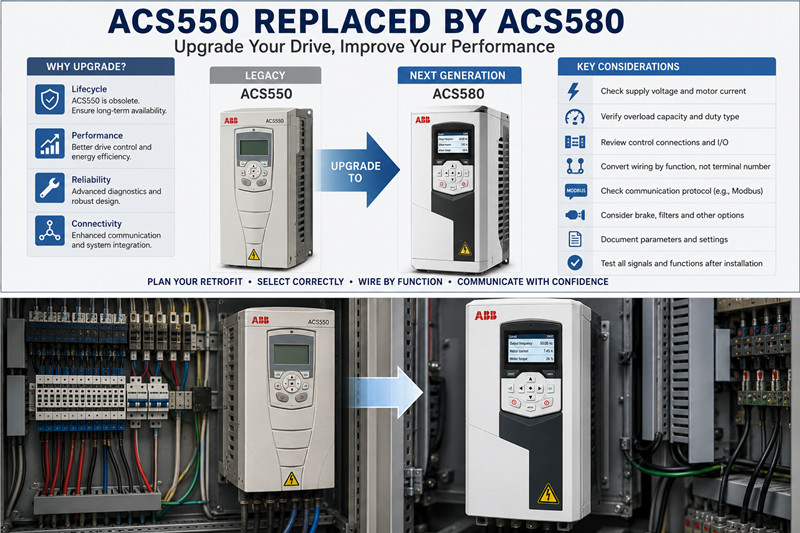
According to ABB's official product roadmap, the direct generational successor to the ACS550 is the ACS580 general-purpose drive. However, concluding that 'ACS550 replaces with ACS580' is only true at a high-level product family level. It does NOT mean that you can perform a blind 1-to-1 swap based purely on motor power (kW / HP).
|
1. Has the ABB ACS550 Been Officially Discontinued?
According to ABB's official 'ACS550, ACH550, and ACQ550 Product Life Cycle Statement', the ACS550, ACH550, and ACQ550 families officially entered the Obsolete life cycle phase on January 1, 2025.
In this statement, ABB notes that for the European, Asian, Middle Eastern, African, and Americas markets, standard production and regular sales have ceased. For specific local markets, remaining availability requires direct inquiry with local ABB entities, and ABB strongly recommends actively migrating installed fleets to next-generation drive families.
Entering the Obsolete phase does not mean every existing ACS550 disappears overnight. In the industrial market, units may still be sourced through:
· Distributor legacy inventory;
· OEM spare parts stock;
· Refurbished, repaired, or pulled equipment;
· Surplus inventory from non-exhausted regional channels.
However, relying on dwindling legacy stock for mission-critical operations exposes plants to soaring component prices, unpredictable delivery lead times, counterfeit risks, and the eventual impossibility of replenishment. Therefore, plants operating ACS550 units must formulate structured migration plans immediately rather than waiting for an emergency breakdown.
2. Successor Families: Which Drive Should You Choose?
ABB has published dedicated replacement and migration guides to help users evaluate capacities, mounting methods, dimensions, electrical parameters, control terminals, and parameter groups between the 550 and 580 series.
|
Legacy Series |
Primary Application Domain |
Next-Gen Replacement Family |
|
ACS550 |
General Machinery, Fans, Pumps, Conveyors, Mixers |
ACS580 (General Purpose) |
|
ACH550 |
HVAC, Building Supply/Return Fans, Chilled Water Pumps |
ACH580 (HVAC Dedicated) |
|
ACQ550 |
Water & Wastewater, Pumping Stations, Sewage Treatment |
ACQ580 (Water/Wastewater) |
|
ACS550 w/ Encoder |
Closed-loop Speed Feedback / High Dynamic Performance |
ACS880 (Industrial High-Performance) |
|
■ MIGRATION RULE OF THUMB |
3. Why You Cannot Swap 1-to-1 Based Solely on Kilowatt Rating
A frequent mistake during field retrofits is assuming that a 15 kW ACS550 can be automatically replaced with any 15 kW ACS580. Motor power is only a nominal reference. The true technical determinants of VFD selection are:
· Mains supply voltage & tolerance;
· Motor rated nameplate current (In);
· Continuous and maximum overload current capacity of the VFD;
· Load profile (Variable Torque vs. Constant Torque / Heavy Duty);
· Ambient temperature & installation altitude derating;
· Motor control method (Scalar vs. Vector);
· Communication network requirements;
· Dynamic braking requirements (braking chopper & resistor);
· Enclosure IP rating and mechanical footprint.
A. Centrifugal Fans and Pumps (Light Duty / Normal Duty)
Fans and centrifugal pumps feature quadratic variable torque load profiles (T ∝ n²), characterized by low starting torque and moderate short-term overload demands. Once the motor current, continuous duty cycle, and ambient conditions are verified, the ACS580 can typically be selected based on its Light Duty (ILd) or Normal Duty rating.
B. Conveyors, Mixers, and Heavy-Duty Loads
Conveyors, heavy mixers, extruders, positive displacement pumps, and hoist mechanisms demand high breakaway torque and endure severe impact loading. For these applications, sizing must account for:
· Actual running current under peak mechanical load;
· Maximum starting/inrush current during acceleration;
· Start/stop duty cycle frequency;
· Locked-rotor / jam risk;
· Low-frequency continuous torque capability.
For such equipment, the ACS580 must be selected based on its Heavy-Duty (IHd) rating, which may require sizing up by one full power frame level.
4. Mandatory Data Collection Prior to ACS550 Removal
Before unmounting the legacy ACS550, compile a complete archival record of the existing installation.
1. Clear Photographic Record of Drive Nameplate
Capture the full hardware code: complete model string (e.g., ACS550-01-038A-4), supply voltage range, rated output current, serial number, IP rating, option codes (+E200, +K454, etc.), and control unit label. A label reading only 'ACS550 15kW' is insufficient for precise engineering replacement.
2. Motor Nameplate Verification
Record: Rated Power (kW/HP), Rated Voltage (V), Rated Current (A), Frequency (Hz), Synchronous/Rated RPM, Power Factor (cos φ), Winding Connection (Star Y vs. Delta Δ), and Motor Type (Standard Induction, PM, or Explosion-proof).
3. Parameter Backup & Control Logic Audit
If the drive powers on, upload parameters via the Assistant Control Panel or DriveWindow Light / Drive composer. If the drive has failed completely, reconstruct the control strategy from electrical schematics, PLC code, and terminal field wiring. Crucial parameter sets include:
· Motor nameplate parameters (Group 99);
· Start/Stop/Direction source & logic (Group 10);
· Min/Max frequencies, Accel/Decel ramp times (Groups 20 & 22);
· Analog Inputs (AI1 / AI2 signal type: 0–10V vs. 4–20mA);
· Digital Inputs (DI1–DI6) & Relay Outputs (RO1–RO3 functions);
· PID controller settings, multi-step speeds, and communication configurations.
5. Control I/O Wiring: Do NOT Wire Pin-to-Pin by Terminal Number
|
■ CRITICAL FIELD WARNING |
|
ACS550 Function |
Signal Type |
ACS580 Equivalent |
Retrofit Action Item |
|
Start / Stop |
Digital Input |
Digital Input |
Verify Active High / DI1 logic setting |
|
Forward / Reverse |
Digital Input |
Digital Input |
Check Macro direction selection |
|
Speed Reference |
0–10 V or 4–20 mA |
Analog Input (AI1/AI2) |
Configure DIP switch / software AI mode |
|
Pressure Feedback |
4–20 mA |
Analog Input |
Verify scale, unit, and PID feedback loop |
|
Running Status |
Relay Output |
Relay Output (RO1/RO2/RO3) |
Re-map relay firmware output function |
|
Fault Output |
Relay Output |
Relay Output |
Verify NO / NC circuit continuity logic |
|
Fault Reset |
Digital Input |
Digital Input |
Configure reset trigger mode (edge/level) |
Crucial Verification Signals: Speed reference (0–10V / 4–20mA), process feedback loops, start/stop interlocks, multi-step speeds, drive run/fault/at-setpoint outputs, bypass interlocks, and emergency fire/safety circuits. Perform a point-to-point I/O check prior to spinning the motor.
6. The Encoder Exception: When You MUST Upgrade to ACS880
A pivotal rule emphasized in ABB migration literature: The ACS580 series does NOT support encoder feedback modules.
If the legacy ACS550 utilized a pulse encoder interface card (such as OTAC-01) for closed-loop vector speed control or precise positioning, the replacement drive MUST be selected from the ABB ACS880 family.
|
7. Modbus Communication Migration Strategies
Both ACS550 and ACS580 support native Modbus RTU communications via standard RS-485 interfaces. However, register mapping is not identical. ABB Technical Note 062 defines two viable migration paths:
Method 1: Enabling Modbus Backward Compatibility Mode
The ACS580 incorporates an embedded legacy compatibility mode that emulates 550-series Modbus register addressing.
· Pros: Minimizes or eliminates PLC/SCADA program modifications; accelerates commissioning and shortens shutdown windows.
· Limitations: Not all legacy parameters are 100% mirrored, and newly introduced ACS580 advanced features/diagnostics cannot be accessed through the compatibility map.
Method 2: Updating PLC / HMI Register Addresses to Native ACS580 Maps
Re-mapping the master PLC, DCS, or HMI software directly to native ACS580 parameter registers. While requiring program adjustments, this provides robust, future-proof communications and full access to modern drive telemetry.
|
8. Physical Footprint, Cabinet Clearance, and Thermal Considerations
The physical chassis dimensions, frame sizing (R1–R9), mounting bolt patterns, and cooling clearance requirements differ between ACS550 and ACS580.
Before ordering, verify inside the enclosure:
· Chassis width, height, and depth;
· Mounting hole coordinates and backplate drill points;
· Upper and lower thermal clearance for airflow exhaust;
· Cabinet door clearance (ensure new drive depth allows door closure);
· Main power and motor cable bend radius and remaining conductor length;
· Braking resistor mounting location and ventilation.
9. Peripheral Accessories: Braking, EMC, and Fieldbus Options
Legacy ACS550 accessories generally cannot be directly ported over to ACS580 without verification:
· Fieldbus Modules: Legacy plug-in adapters (RPBA-01 Profibus, RDNA-01 DeviceNet) must be replaced by modern F-series adapters (FPBA-01, FDNA-01, FENA-21 for Ethernet/IP & PROFINET).
· Braking Resistors: Re-verify internal chopper availability (integrated in smaller frames) and minimum allowable braking resistance (Ω) and thermal power (kW).
· EMC & Reactors: ACS580 features integrated harmonic mitigation (swinging choke equivalent) and standard EMC filtering.
· Safe Torque Off (STO): ACS580 includes dual-channel SIL3 / PL e STO terminals natively, requiring proper hardwired jumpering or integration into emergency safety circuits.
10. Recommended 9-Step Field Migration Workflow
· Step 1: Build Existing Machine Archive — Photograph nameplates, wiring, cabinet layout, and existing options.
· Step 2: Backup Parameters & PLC Programs — Export parameter files, capture schematics, and record Modbus register maps.
· Step 3: Analyze Load Characteristics — Classify mechanical load (variable vs. constant torque) and record operational amp draw.
· Step 4: Select Proper ACS580 Sizing — Size according to voltage, full-load amps, overload cycle, and ambient rating.
· Step 5: Audit Special Requirements — Confirm encoder presence, PID loops, fieldbus protocols, dynamic braking, and STO circuits.
· Step 6: Construct Cross-Reference Tables — Create detailed mapping sheets for Power Terminals, Control I/O, Parameters, and Comm Registers.
· Step 7: Perform Pre-Installation Offline Commissioning — Bench-test the new drive, pre-load parameters, and verify communications before plant downtime.
· Step 8: Execute Cold & Hot Commissioning — Test motor rotation direction, start/stop logic, speed scaling, PID loop response, and emergency stop interlocks.
· Step 9: Archive Final Documentation — Save final parameter backups, revised electrical drawings, and full ordering codes for plant records.
11. Seven Common Replacement Mistakes to Avoid
· Mistake 1: Sizing by Motor kW Alone: Overlooking rated current, ambient derating, and heavy-duty overload requirements.
· Mistake 2: Terminal-for-Terminal Blind Rewiring: Assuming identical terminal number assignments between generations.
· Mistake 3: Failing to Backup Parameters: Attempting to reconstruct complex PID or multi-step logic from scratch after drive failure.
· Mistake 4: Overlooking the Encoder: Installing a standard ACS580 on a closed-loop encoder application instead of an ACS880.
· Mistake 5: Assuming Identical Modbus Registers: Neglecting register shift, word order, or scaling factor differences.
· Mistake 6: Ignoring Cabinet Physical Dimensions: Discovering mounting hole mismatches or insufficient door clearance on install day.
· Mistake 7: Overlooking Option Modules: Omitting required fieldbus gateways, braking units, or I/O extension modules from the order.
12. Official ABB Reference Documents
1. ABB ACS550, ACH550, and ACQ550 Product Life Cycle Statement
Details obsolescence timeline, regional availability guidelines, and phased migration pathways.
2. ACS550 to ACS580 Replacement and Comparison Guide (Doc # 3AXD50000660681)
Comprehensive technical cross-reference: frame sizes, clearances, wiring terminals, and parameter groups.
3. 550 to 580 Series Modbus Register Conversion (Technical Note 062)
Implementation guide for Modbus RTU backward compatibility mode and native register translation.
4. ABB ACS580 General Purpose Drives Hardware Catalog (Doc # 3AUA0000145061)
Full technical specifications, complete ordering nomenclature, dimensional drawings, and option codes.
|
■ IMPORTANT SAFETY & ENGINEERING NOTICE |
🏢 About TZ Tech
TZ Tech is a leading supplier of industrial automation, electrical, instrumentation, and telecommunications components. We specialize in sourcing ready-to-ship distributor stock, allowing us to offer highly competitive pricing and short lead times. Thanks to our extensive inventory, we can even source rare and discontinued parts that are hard to find elsewhere.
🛡️ Our Quality Commitment
We understand that quality is your top priority. Every component undergoes a strict screening and inspection process so you can buy with absolute confidence. For legacy or discontinued parts, we believe in complete transparency and will always provide an honest, accurate report on the product's condition. Plus, all brand-new parts come backed by a full 1-year warranty.
✉️ Get in Touch
Have a project or a part you need? Send us your inquiry today! Our team is dedicated to providing a fast response within 6 hours (excluding weekends).


Please read on, stay posted, subscribe, and we welcome you to tell us what you think.


Sitemap | Blog | XML | Privacy Policy
In addition, with your permission, we want to place cookies to make your visit anointeraction with slOC more personal. For this we use analytical and advertisingcookies. With these cookies we and third parties can track and collect yourinternet behawior inside and outside super-instrument.com. With this we and third parties adapt super-instrument.com and advertisementsto your interest. By clicking Accept you agree to this. If you decline, we only usethe necessary cookies and you unfortunately will not receive any personalizedcontent. Please visit our Cookie policy for more information or to change yourconsent in the future.
Accept and continue Decline cookies