
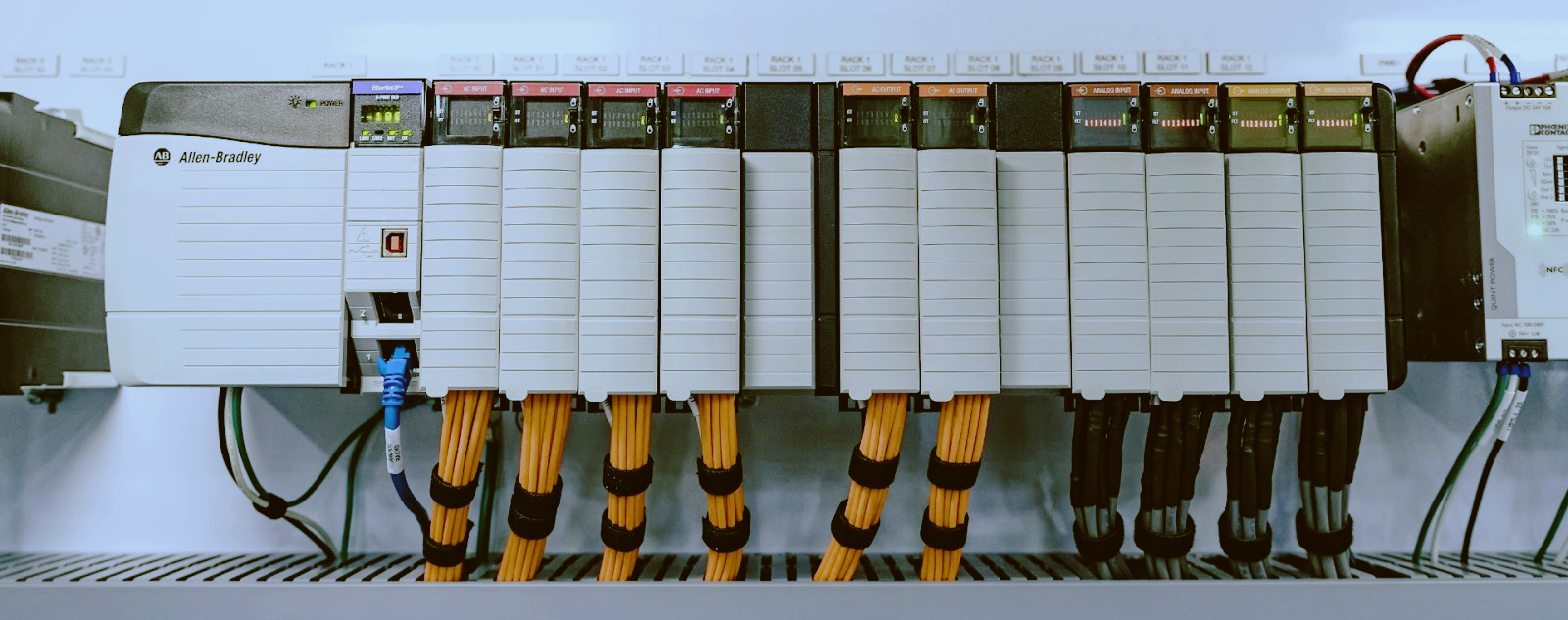
Siemens S7-300 Analog Input Troubleshooting: SM331 Faults Found in the Field
Three in the morning. The packing line goes quiet. Not the graceful quiet of a planned stop. The kind that makes the night operator call me with a voice that says this is not the first problem tonight.
"The tank level reads full," he says. "Full and climbing. We're about to put product on the floor."
I pull up the VAT table on my laptop. The raw word for the level channel sits at 27648. Pegged hard at the top of the scale. The transmitter on that tank is a 4-20 mA unit, and 27648 is what the SM331 reports when the input is maxed out. Either the tank really is overflowing, or something in that loop is lying.
It was the loop. It usually is.
I've replaced more SM331s than I can count. I've also watched perfectly good modules get condemned because a 2-wire transmitter got wired into a slot set up for 4-wire, or a range card went back in backwards after a panel cleaning. Nine times out of ten it's not the module. It's the stuff hanging off the terminals.
This article is the order I check things in, ranked by how often I actually see each fault in the field. Work the list top to bottom before you order a spare. You'd think the module is the problem. Most nights, it isn't.
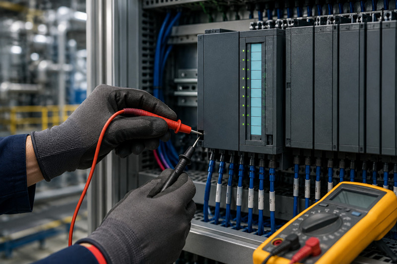
The SM331 is the analog input card for the S7-300 family. It takes the 4-20 mA, 0-20 mA, or voltage signal from a field transmitter and turns it into a number the CPU can use. That number is a raw integer between 0 and 27648 for unipolar ranges, or between -27648 and +27648 for bipolar ranges. The CPU then scales that raw value into engineering units: percent, bar, or degrees Celsius. Whatever the process needs.
The whole family shares a few traits. They mount on the same rail. They use the same backplane bus. They all answer to the same diagnostic system. The differences are in the channel count, the resolution, the input ranges, and how well the channels are isolated from each other.
One thing I tell every apprentice: an SM331 is a dumb, honest device. It does not invent readings. If it reports 27648, something drove the input there. If it reports zero, the loop is open or dead. The card is a voltmeter with a serial number. Treat it that way and troubleshooting gets a lot simpler.
Not all SM331s are the same. The order number tells you almost everything. These are the ones I actually see in plants, with what they're good for.
Order number | Channels | Resolution | Input ranges | Typical use
6ES7331-7KF02-0AB0 | 8 AI | 12-bit | 0-20 mA, 4-20 mA, ±10 V | The workhorse. Process signals, transmitters, drive feedback
6ES7331-7KB02-0AB0 | 2 AI | 12-bit | 0-20 mA, 4-20 mA, ±10 V | Small panels, a couple of signals, retrofits
6ES7331-7NF10-0AB0 | 8 AI | 15-bit | 0-20 mA, 4-20 mA, ±10 V | High resolution, precision weighing, fast loops
6ES7331-7NF00-0AB0 | 8 AI | 15-bit | 0-20 mA, 4-20 mA, ±10 V | Older high-res card, same job as the 7NF10
6ES7331-1KF02-0AB0 | 8 AI | 13-bit | 0-10 V, ±10 V, 0-20 mA | Voltage-heavy panels. No isolation between channels
6ES7331-7PF11-0AB0 | 8 AI | 16-bit | RTD, thermocouple | Temperature. Pt100, type J and K
A few notes from the field. The 7KF02 is the one you'll pull out of most racks. It's cheap, it's everywhere, and the range card lets one card handle voltage, current, and on some positions even Pt100 and thermocouples. That flexibility is why it survived so long.
The 1KF02 has no isolation between channels. Every channel shares the same reference. A ground fault in one loop drags the whole card. I've seen one bad field cable take down all eight channels at once, and the maintenance crew replaced two perfectly good cards before somebody checked the cable.
The 7NF10 uses a 40-pin front connector. The 7KF02 and the 1KF02 use 20-pin. When you buy a replacement, match the connector, or you'll be hunting for the right cable at 2am.
This is the big one. I'd say half of my analog calls end with a screwdriver fix, not a parts order. The most common mistake is reversed polarity on the channel terminals. M+ and M- swapped. An instrument tech re-terminates a pressure transmitter after a calibration, gets the pair crossed, and the reading dies. The operator swears the transmitter is dead. The transmitter is fine. The two little letters on the terminal block are the whole story.
Current inputs need a return path. If the negative side of the loop is floating, you get garbage. Not zero, not pegged. Garbage. Values that wander around like a drunk man. I've also seen a terminal that looked tight but had a strand of wire hanging by a thread. The reading dropped every time the machine vibrated. You'd think it was a loose sensor. It was a loose screw.
Checks:
· Are the terminal screws actually tight? Pull on each wire, not gently.
· Is M+ on the module going to the plus side of the signal? Is M- going to the minus?
· Does every current channel have a complete return path?
· Any corrosion, green fuzz, or discolored terminals in wet areas?
Fix: re-terminate with ferrules, replace damaged terminal blocks, and label the pair. A label costs ten seconds and saves an hour.
This one sends good modules to the scrap bin. A 2-wire transmitter is powered by the loop itself. The module has to be configured for 2-wire operation so it feeds loop power out of the channel. A 4-wire transmitter runs on its own supply. Its output is just a signal, and the module only measures it.
Wire a 2-wire transmitter into a slot configured for 4-wire and there is no loop power. The card reads zero. Everybody blames the card. I found a brand-new pressure transmitter like that once, installed by a contractor, dead on arrival according to the foreman. It took me two minutes with a multimeter to find the loop had no voltage on it. The card never had a chance.
The reverse is worse. Wire a 4-wire transmitter into a slot configured for 2-wire and the module tries to drive loop current into an output that can't sink it. The reading pegs at 27648 and the transmitter output stage gets hot and unhappy. That's the "tank is full" call at 3am, sometimes with a genuinely full tank because the valve closed on a false reading.
Checks:
· How many wires go to the transmitter? Two means 2-wire. Four means it has its own power pair.
· What does the HW Config entry say for that channel group?
· What position is the range card in?
Fix: set the range card and the HW Config to match the transmitter type, and land the loop supply where it belongs.
The classic. A raw value pinned at 27648 means the input is being driven to maximum. A raw value pinned at 0 means the loop is open, the sensor is dead, or the supply is missing. Both look identical on the HMI: a bad reading. Both have completely different causes.
Pegged at 27648, in order of likelihood: the sensor is shorted or pegged, the loop current really is above 20 mA, the transmitter output is saturated, or the range is set wrong. I had a tank level that read full for a week. The operator wrote it off as a faulty card. The cable had been pinched under a cable tray during a roof job, shorting the pair together. The transmitter was pushing its maximum against a shorted loop. The card was reporting the truth.
Stuck at 0: an open loop, a dead transmitter, a blown fuse on the 24V loop supply, or a wire break with monitoring turned off. And here's a subtle one: if the channel is configured for 0-20 mA but the transmitter is 4-20 mA, the card reads about 20% of scale when the tank is empty. Not zero. Twenty percent. Operators call that "leaking" and it's a config problem, not a hardware problem.
Checks:
· Put a mA meter in series with the loop. What does the current actually read?
· Measure voltage across the transmitter terminals. Is it getting what it needs?
· Check the 24V rail and the loop fuse. Fuses die at 3am more than any component.
Fix: replace the fuse, repair the cable, or replace the sensor. Then inject 12 mA with a loop calibrator. If the card reads mid-scale, the card was never the problem.
The 7KF02 isolates its channels in groups of two. Channels 0 and 1 share a group. So do 2 and 3, 4 and 5, 6 and 7. When one channel in a group takes a hit, its partner rides along. I've seen a surge take out the input protection on channel 0, and channel 1 read nonsense for a month while everybody blamed the transmitter on channel 1.
The group wiring also shares the reference. A shorted field cable on one channel in the group can pull the group's reference and drag the neighbor's reading. Same group, same fate.
Checks:
· Move the suspect signal to a channel in a different group. If it reads fine there, the group is damaged, not the whole card.
· Check both channels in the group. If they both misbehave, suspect the group.
· Look at the field cable on both channels, not only the one that's alarming.
Fix: repair the faulted field path. If the input stage of that group is genuinely blown, the card has to go. You can't bypass a dead group.
The 7KF02 has a range card, a little board you slide into the front of the module. It sets the measurement range for each channel group. It can go in backwards. It can go into the wrong slot. I watched a panel cleaning crew pull one, wipe the contacts, and put it back rotated 180 degrees. Half the channels read nonsense after that. Nobody touched the program. Nobody touched the wiring. A $5 piece of plastic was the whole fault.
The range card position and the HW Config entry have to agree. If the card says 4-20 mA but HW Config says 0-10 V, the readings will be wrong in a way that looks like a sensor problem. And the order number and hardware version in HW Config have to match the actual module, or the CPU flags the slot.
Checks:
· Pull the range card. Is it the right way around? Is it in the right position?
· Does HW Config show the same range for that group?
· Does the order number in HW Config match the module in the rack?
Fix: reinsert the card correctly, correct the HW Config entry, and download. Reboot the rack if the CPU is grumpy about it.
The 7KF02 only separates its channel groups by about two volts. That is not real isolation. It's a token separation. If the transmitter and the PLC sit on different ground potentials, the difference lands right on the input. Readings drift. They jump. Sometimes they peg.
I had a compressor skid built in the States, running 120V/60Hz, sitting next to a 230V/50Hz plant panel. The analog signal drifted all day long. The grounds disagreed by a couple of volts and the 7KF02 had no headroom for it. The fix was a single-point ground and a shield grounded at one end. The 15-bit 7NF modules handle this kind of thing better, but you can't always pick your hardware.
Checks:
· Measure the voltage between the transmitter negative and the module M- terminal. More than a volt or two is a common-mode problem.
· Is the shield grounded at both ends? That's a ground loop with a hum.
· Are the signal cables sharing a tray with motor leads or VFD cables?
Fix: single-point grounding, one end of the shield grounded and the other taped, and in stubborn cases an isolator between the transmitter and the card. It costs less than a new module and it fixes the root cause.
The module is in slot 4 and the config says slot 5. Or the order number in HW Config doesn't match the card that's actually installed. The CPU either faults the slot or the values never update. The HMI shows stale numbers and the operators think the process is frozen.
I've also been handed a "new" module from stores that was an older hardware version than what HW Config expected. The CPU refused to accept it. The fix was matching the version in the config to the card in the rack, or finding the right card. Check the input word addresses too. An 8-channel card takes eight words, and if two cards overlap on addresses, you get readings that fight each other.
Checks:
· Open Module Information in HW Config. Does the card report the order number and version you expect?
· Is the module in the slot the config says it's in?
· Do the input word addresses overlap with another card?
Fix: correct the config, download, and confirm the addresses. Then verify the live value in a VAT table.
Last on the list, and it should be. Real hardware failure happens. A surge takes out an input stage. A shorted transmitter pumps 24V into an input that was only rated for milliamps. Lightning lands on a fence line a hundred meters away and the whole rack flinches. Sometimes a card just dies of old age.
The signs are honest: SF LED steady on, Module Information showing an internal fault, no channel responding even with a calibrator directly on the terminals, and the fault follows the card when you move it to another slot. If you've done steps 1 through 7 and the card still won't behave, it's the card.
Checks:
· Swap test with a known-good card. Fault follows the card? It's the card.
· Smell the module. Burnt electronics have a distinctive smell. So does a blown input protection stage.
· Look for visible damage on the input circuitry.
Fix: replace it. Match the order number exactly and check the hardware version against your HW Config entry. A used 6ES7331-7KF02-0AB0 from a reputable supplier is fine. Just confirm the version and that the range card comes with it. Front connector type matters too. If you're shopping, we carry Siemens PLC spare parts and general PLC spare parts that cover the common SM331 versions, new and used. New modules carry CE and UL markings. Used ones from the EU or the States are fine as long as the order number and version match.
The SF LED is the module's whole vocabulary. Learn it and you skip half the guesswork.
LED state | Meaning | What to do
SF off | No fault reported by the card | Trust it, but still check the field wiring
SF flashing | Channel fault: wire break, overrange, underrange | Read the diagnostics, find the channel
SF steady on | Parameter assignment error or internal fault | Check HW Config, range card, and module version
In HW Config, double-click the module and open Module Information. The Diagnostics tab is where the card tells the truth. It names the channel, the fault type, and whether it's a wire break, an underrange, or an overrange. It also shows internal faults that the LEDs can't express.
If you enable the diagnostic interrupt in the module parameters, the CPU gets notified on every fault. That's where the trap is. If the interrupt is enabled and OB82 is not loaded in the program, the CPU goes to STOP the first time a channel faults. I've answered that call at 3am. Someone enabled diagnostics for a good reason and forgot the OB. The whole line stopped because one spare channel had a loose wire.
Open a VAT table and enter the input word address. For an 8-channel card, that's eight words. Watch the value while you inject a known signal at the field terminals. If the raw value follows the signal, the card and the config are fine. If the raw value ignores the signal, work back toward the field, terminal by terminal.
Wire break monitoring is parameterizable on the 4-20 mA and 1-5 V ranges. When it's on, an open loop reads 32767 and the SF LED flashes with a wire break diagnostic. When it's off, an open loop reads 0 and looks exactly like a dead sensor. Know which setting you have, or you'll chase a ghost for an hour.
Here's the map I keep in my head. Raw values are integers, and the scale is fixed.
Raw value | Percent of range | 4-20 mA signal | What it usually means
32767 | overrange | above 20 mA | Wire break with monitoring on, or overrange
27648 | 100% | 20 mA | Input maxed. Sensor pegged, short, or wrong range
20736 | 75% | 16 mA | Normal reading at 75%
13824 | 50% | 12 mA | Mid-scale. Normal
6912 | 25% | 8 mA | Normal reading at 25%
0 | 0% | 4 mA | Zero signal, open loop, or dead transmitter
-32768 | underrange | below 4 mA | Underrange with monitoring on
One thing that trips people up: on the 4-20 mA range, the module maps 4 mA to raw 0 and 20 mA to raw 27648. The dead zero of the 4-20 range is already removed inside the card. So when you scale, the low limit is the engineering value at 4 mA, not the value at 0 mA. Get that backwards and your tank reads full when it's empty.
FC105 is the SCALE function in the standard library. IN is the raw integer from the input word. HI_LIM and LO_LIM are your engineering range. BIPOLAR tells the block whether the raw range is -27648 to +27648 or 0 to 27648. OUT is the real result. RET_VAL is the status word, and you should check it. If it's not zero, the conversion has a problem.
Most scaling bugs I see are a wrong BIPOLAR flag or swapped limits. Both produce readings that are wrong in a very consistent way, which makes operators trust them more, not less. A reading that's always 10% high is a scaling bug until proven otherwise.
The module feeds the loop power. L+ lands on the module's L+ terminal. The loop current comes out of the channel's M+ terminal, through the transmitter, and back into M-. No external supply needed. If the module isn't configured for 2-wire, there's no loop power and the reading sits at zero, waiting for you to blame the card.
The transmitter runs on its own supply. The signal pair goes to M+ and M-. Do not feed loop power from the module into a 4-wire transmitter output. The card pegs and the transmitter output stage gets hot. I've replaced two transmitters before I found a contractor doing exactly that.
Twisted shielded pair for 4-20 mA, always. Ground the shield at one end only. Pick the panel end or the field end and stay consistent. Both ends grounded is a ground loop with a nice hum. Keep signal cables out of the tray with the motor leads and the VFD cables. I've seen a VFD turn a clean 4-20 mA signal into noise you could hear on a radio. The card reads it as a signal. The process reads it as chaos.
· Terminals: tight, clean, ferruled, with M+ and M- correct.
· Loop: meter in series, confirm the current matches the process.
· Supply: 24V at the loop, fuse good, polarity right.
· Config: range card position, HW Config order number, hardware version, measurement range.
· Isolation: move the signal to another channel group, inject with a calibrator.
· Then the card.
Do it in that order and you'll replace a lot fewer modules. I keep a loop calibrator in my truck. It has paid for itself a hundred times over. A $200 tool that proves the card is fine is cheaper than a $400 module that isn't the problem.
Replace the module when the SF LED is steady on with an internal fault in diagnostics. Replace it when no channel responds, even with a calibrator directly on the terminals. Replace it when the fault follows the card to another slot. Replace it when you can smell burnt components. Surge damage on an input stage is not repairable on the floor. Don't waste a shift on it.
When you buy the replacement, match the order number exactly. Check the hardware version against your HW Config entry. Confirm the front connector type. Confirm the range card is included. A module without its range card is a paperweight on the 7KF02. We stock Siemens PLC spare parts with the versions listed, so you can match before you order instead of after.
· Every shutdown: check terminals for tightness and corrosion.
· Pull the range card, inspect the contacts, reinsert it correctly.
· Verify shield grounds are single-ended.
· Log raw values for healthy channels so you know what normal looks like.
· Check the 24V rail and the loop fuses.
Hot tags : Siemens S7-300 SM331 SM331 Faults

Please read on, stay posted, subscribe, and we welcome you to tell us what you think.


Sitemap | Blog | XML | Privacy Policy
In addition, with your permission, we want to place cookies to make your visit anointeraction with slOC more personal. For this we use analytical and advertisingcookies. With these cookies we and third parties can track and collect yourinternet behawior inside and outside super-instrument.com. With this we and third parties adapt super-instrument.com and advertisementsto your interest. By clicking Accept you agree to this. If you decline, we only usethe necessary cookies and you unfortunately will not receive any personalizedcontent. Please visit our Cookie policy for more information or to change yourconsent in the future.
Accept and continue Decline cookies