Siemens ET 200M & IM 153 Engineering Reference Guide
Sep 22, 2026
System Architecture, Module Compatibility, Power Budgeting, and Diagnostics
1. Overview & System Architecture
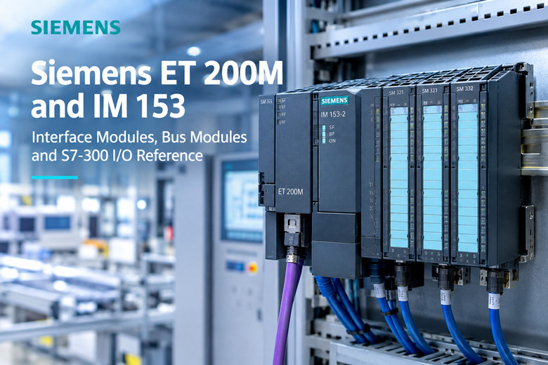
The Siemens ET 200M is a modular distributed I/O station designed to mount standard S7-300 signal modules on an S7-300 profile rail (IP20 rating). It bridges field I/O back to a central programmable logic controller over a single bus link, substantially reducing panel wiring, terminal counts, and commissioning overhead. ET 200M stations contain no user logic or retentive process data; control remains strictly with the PLC CPU.
An operational ET 200M station consists of five core hardware assemblies:
· Profile Rail & Bus Modules: Active backplane bus modules (BM PS, BM IM, BM IM/IM) allow hot swapping without interrupting adjacent operational modules.
· Interface Module (IM): IM 153-1, IM 153-2, IM 153-2 FO, or IM 153-4 PN managing communication, backplane power delivery, diagnostics, and redundancy.
· Signal Modules (SM): Standard S7-300 digital and analog input/output modules (SM 321, SM 322, SM 323, SM 331, SM 332, SM 334, and fail-safe SM 336).
· Function & Communication Processors (FM/CP): High-speed counter modules (FM 350-1), positioning modules (FM 351), and serial communication modules (CP 340/341).
· Power Supply & Field Connectors: Optional PS 307 load power supplies (2A/5A), front connector blocks (20-pin / 40-pin), and bus shielding hardware.
2. Interface Module (IM 153) Selection
Interface modules establish the fieldbus network and define redundant capabilities:
· IM 153-1 (PROFIBUS DP): Standard single-interface module supporting baud rates from 9.6 kbit/s up to 12 Mbit/s. Suitable for non-critical, non-redundant stations. DP node address is configured directly via on-module DIP switches.
· IM 153-2 / IM 153-2 FO (PROFIBUS DP): High-feature interface supporting bumpless active redundancy when paired with an S7-400H redundant master. The fiber-optic (FO) version provides galvanic isolation across lightning-prone or high-EMI industrial runs.
· IM 153-4 PN (PROFINET IO): Industrial Ethernet interface operating at 100 Mbit/s full-duplex. Features an integrated 2-port switch enabling daisy-chain line topologies without external network switches.
3. Power Budgeting & Mechanical Layout
A reliable ET 200M station requires careful calculation of two distinct electrical circuits before populating slots:
· Backplane Current Budget: The IM supplies internal logic power across the backplane bus. Sum the backplane draw of all inserted SM/FM/CP modules and ensure the aggregate does not exceed the IM rated supply limit to avoid intermittent trip-outs.
· 24 V DC Load Supply: Field sensors, actuator coils, and digital output transistors draw from an isolated external 24 V DC supply. Factor in a 25% to 30% margin over nominal current for inductive inrush. Verify voltage levels at the furthest end of the rail to prevent drop-induced channel dropouts.
· Slot Capacity: A single rack accommodates up to 8 S7-300 I/O modules. Single-IM configurations consume slot 1; redundant architectures utilize a BM IM/IM spanning slots 1 and 2.
4. Hardware Configuration & Lifecycle Migration
· Engineering Environment: STEP 7 V5.x (HW Config) configures PROFIBUS DP and S7-400H setups. TIA Portal and GSDML device definitions manage IM 153-4 PN stations. Verify GSD/GSDML revision accuracy to ensure station connectivity.
· Migration & Coexistence: For installations migrating toward S7-1500 controllers, existing ET 200M stations can either be integrated via IM 153-4 PN or bridged to PROFINET through DP/PN Couplers or IE/PB Links, preserving existing wiring and spare inventories.
· Order Number (MLFB) Rigor: Always match the complete MLFB tail after the second hyphen (e.g., 6ES7 321-1BH02-0AA0 vs older variants) to guarantee exact diagnostic capabilities, isolation ratings, and interrupt response times.
5. Troubleshooting & Maintenance Guide
· IM Bus Fault (BF Solid / Flashing): Indicates duplicate node addresses, station absent from PLC hardware configuration, baud rate mismatch, unpowered end-of-line terminators, or reversed PROFIBUS A/B lines. Always inspect master slave diagnostics first.
· Intermittent Faults on Drive Start: Noise induced on signal lines. Bond cable shields directly to cabinet ground bars using 360-degree shield clamps. Route communication cables in dedicated trays separate from VFD motor leads.
· Individual Channel Failure: A healthy module with isolated dead outputs indicates external 24 V DC load voltage loss or thermal overload trip. For analog channels stuck at min/max limits, inspect sensor polarity, wire breaks, or common-mode ground loops.
· Hot-Swap Procedure: Slide the front connector off the faulty module without disturbing field wiring. Disengage the mechanical latch, replace the module onto the active bus module, remount the front connector, and confirm LED recovery and diagnostic buffer clearance.