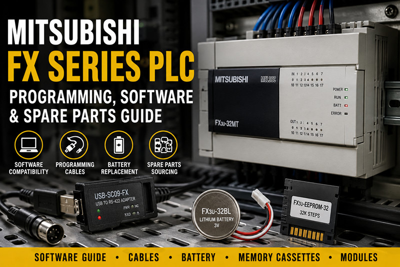
PLC ENGINEERING

Blog

Home

Blog

  • How PLCs Run Water Treatment Plants in the Middle East and Europe: 2026 Automation Guide
    How PLCs Run Water Treatment Plants in the Middle East and Europe: 2026 Automation Guide May 20, 2026
      URL Slug: plc-water-treatment-automation-middle-east-europe-2026 The Invisible Infrastructure PLC in water treatment plants automation Middle East Europe 2026 — search this and you get vendor pages, academic papers, and a few outdated white papers. What you do not get is a straight answer from someone who has actually specified the hardware for a working plant. This article fixes that. It covers how PLCs actually run water and wastewater treatment facilities: which platforms are deployed, what they control, how they integrate with SCADA, and what the regulatory landscape looks like in 2026 for both regions. The reason this matters: water treatment is one of the most demanding PLC applications because it combines continuous process control, safety-critical chemical dosing, harsh environments (corrosive atmospheres, humidity), and regulatory reporting requirements that make SCADA integration non-negotiable. A PLC failure in a water treatment plant is not an inconvenience — it can be a public health event.   What PLCs Control in Water Treatment Plants A modern municipal or industrial water treatment plant automates four core processes: chemical dosing, aeration, filtration, and backwash cycles. PLCs also handle auxiliary functions like pumping, level control, and flow balancing. The complexity varies significantly between a small package plant (a few thousand gallons per day) and a large metropolitan treatment facility (hundreds of millions of gallons per day). Chemical Dosing Chemical dosing is the most safety-critical function. Chlorine (or chloramine) dosing prevents pathogen breakthrough. Coagulants (aluminum sulfate, ferric chloride) aggregate suspended solids. pH adjustment chemicals (lime, sulfuric acid) correct alkalinity. Phosphorus removal chemicals (ferric chloride, alum) target nutrient loads. The PLC controls dosing pumps in response to online analyzer readings. A typical configuration: · Flow transmitter on the inlet header (measures flow rate, GPM) · Residual chlorine analyzer downstream of the contact tank · PLC calculates the required dose rate (mg/L) based on flow-proportional dosing · Analog output (4–20mA) drives the dosing pump stroke or speed Siemens S7-1500 systems handle this well in UAE municipal projects — the built-in PID control functions (PID_Compact, PID_3Step) are well-suited for dosing loops, and the TIA Portal libraries include pre-built water treatment function blocks that reduce programming time. Allen Bradley ControlLogix with 1756-IF8 analog inputs and 1756-OF4 analog outputs handles the same function in US plants — the RSLogix and Studio 5000 environment is familiar to US water utilities, and the Allen Bradley platform has deep integration with Rockwell Automation PlantPAx process automation system. Aeration Control Aeration serves two purposes: biological oxidation of organic matter (BOD removal) and maintaining dissolved oxygen (DO) levels for nitrification. In activated sludge processes, the PLC modulates aeration air flow to each aeration basin based on DO readings from online probes. A typical aeration control loop: · DO probe (polarographic or optical) in each aeration basin · PLC reads DO (4–20mA signal) · PLC adjusts the air damper or blower VFD speed via analog output or Modbus/Profibus to a variable frequency drive · Goal: maintain DO setpoint (typically 2 mg/L) while minimizing energy consumption ABB AC500 systems are common in European water utilities, including a Spanish regional water company that operates multiple treatment plants on the Mediterranean coast. The ABB platform's AC500 CPU handles the computational load of multi-zone aeration control (which requires coordinating DO readings across 4–8 aeration basins simultaneously) and integrates cleanly with the utility's existing ABB VFDs over Modbus RTU. The ABB automation builder platform also includes a water treatment library that covers aeration control, sludge wasting, and chemical dosing — useful for standardization across a multi-plant operator. Filtration and Backwash Cycles Granular media filtration (sand filters, multimedia filters) removes suspended solids. The filtration cycle runs in production mode until a headloss setpoint is reached (indicating filter fouling), at which point the PLC initiates a backwash cycle. The backwash sequence: 1. Drain down the filter (controlled via automated weir valve) 2. Air scour (air scour blower for 2–5 minutes) 3. Slow rinse (filtered water for 2–5 minutes) 4. Return to service The PLC executes this sequence using ladder logic or structured text, with interlock logic preventing the filter from returning to service until the full sequence completes. Timing is critical — too short a backwash and the filter carries forward solids; too long and you waste treated water and energy. In the Middle East, many plants use dual-media filters (anthracite + sand) with automated backwash controlled by Siemens S7-1500 PLCs. The S7-1500 system's high-speed counter inputs handle the flow totalization required for backwash volume tracking, and the built-in RTC (real-time clock) timestamps backwash events for regulatory logs. SCADA Integration No modern water treatment PLC operates in isolation. Plant-level PLCs communicate with a SCADA (Supervisory Control and Data Acquisition) system that provides: · Real-time visualization of process parameters (tank levels, flows, DO, chlorine residual) · Historical data logging and trending · Alarm management and escalation · Regulatory reporting (monthly DMRs in the US, EU Water Information System in Europe) Common SCADA platforms in the Middle East: Siemens WinCC (often paired with S7 PLCs), Wonderware (Schneider Electric), and Ignition (Inductive Automation). In Europe, you see a wider mix: WinCC, Rockwell Automation FactoryTalk, and PI System (OSIsoft) for historians. Communication protocols: Modbus RTU (serial, common in legacy European plants), Modbus TCP/IP (Ethernet, increasingly common), Profinet (Siemens plants), EtherNet/IP (Allen Bradley plants), and OPC-UA (for IT/OT integration and multi-vendor plants). --- Regional Regulatory Landscape Middle East: UAE DEWA Standards The Dubai Electricity and Water Authority (DEWA) sets standards for water treatment automation in the UAE. DEWA's regulatory framework requires: · Online monitoring and data logging for all critical parameters (flow, pressure, chlorine residual, turbidity) · Alarm management with defined response procedures · Periodic calibration records for all instruments (pH, chlorine, flow) · SCADA integration with DEWA's central monitoring system for large-capacity plants Siemens S7-1500 with TIA Portal is the most common platform for new UAE municipal water projects because Siemens has strong local support in Dubai and Abu Dhabi, DEWA engineers are familiar with the platform, and the S7-1500 system supports the Profinet protocol required for integration with DEWA-compliant SCADA systems. UAE projects typically specify ABB or Siemens for new plants, with Allen Bradley appearing more in industrial (non-municipal) water treatment, particularly at petrochemical complexes where the parent company has an existing Allen Bradley infrastructure. Pricing signals: UAE municipal water treatment projects (particularly those funded by government infrastructure budgets) have remained robust through 2025–2026, with no significant slowdown in new plant construction or upgrades. Budget allocations for automation upgrades at existing plants are increasing as operators prioritize energy efficiency (aeration is the largest energy consumer in a typical activated sludge plant). Europe: EU Water Framework Directive The EU Water Framework Directive (WFD, 2000/60/EC) and its daughter directives set the regulatory baseline for water treatment across the EU. Key requirements affecting PLC and automation specifications: · Mandatory monitoring of priority substances and chemical status · Real-time continuous monitoring for certain parameters (ammonia, nitrate, DO) · Electronic reporting to the Water Information System Europe (WISE) · Energy efficiency requirements increasingly driving aeration optimization projects European water utilities are more conservative about platform changes than Middle Eastern operators — an existing ABB AC500 installation at a Spanish water utility will typically be expanded or upgraded with ABB modules rather than migrated to a competing platform, due to the cost of re-engineering and re-validation. Allen Bradley ControlLogix is common in Northern European water utilities (UK, Netherlands, Scandinavia) where the Rockwell Automation ecosystem has strong local support. The UK's water sector (operated by companies like Thames Water, Severn Trent, United Utilities) uses Allen Bradley extensively, and many treatment works have been upgraded with ControlLogix as part of AMP (Asset Management Programme) investment cycles. Platform Choices in Practice: Three Real-World Examples UAE: Dubai Municipal Treatment Plant — Siemens S7-1500 A 50 MLD (million liters per day) municipal water treatment plant in Dubai uses a Siemens S7-1500 (CPU 1516-3 PN/DP) as the main PLC, with ET 200SP distributed I/O on the process units. TIA Portal handles programming, with custom function blocks for chemical dosing and aeration PID loops. The SCADA system is Siemens WinCC OA. The plant operates under DEWA oversight, with data pushed to DEWA's central monitoring system via OPC-UA. The dosing system uses 4–20mA loops from Siemens SM531 analog input modules to the dosing pump VFDs, with PID_Compact controllers managing chlorine and coagulant dosing. Spain: Mediterranean Coastal Utility — ABB AC500 A Spanish regional water company operates 12 treatment plants across the Valencia and Catalonia regions. The standard platform is ABB AC500 (PM573-ETH CPU) with S500 I/O modules. Automation Builder (CODESYS-based) provides the engineering environment. The largest plant (85 MLD) uses a multi-zone aeration control strategy coordinated across 6 aeration tanks. The ABB platform's ability to handle multiple Modbus RTU networks (one per aeration basin) on a single CPU was a key selection criterion. SCADA is Wonderware InTouch with an OSIsoft PI historian for regulatory reporting to the Spanish Ministry of Environment. USA: Midwestern Wastewater Treatment Plant — Allen Bradley ControlLogix A 35 MGD (million gallons per day) municipal wastewater treatment plant in the US Midwest uses an Allen Bradley ControlLogix system (1756-L85E CPU, 1756-IF8 / 1756-OF4 analog modules, 1756-IB16 / 1756-OB16 digital modules) for secondary treatment control. The plant runs a conventional activated sludge process with chemical phosphorus removal. Dosing pumps (aluminum sulfate and polymer) are controlled via 4–20mA signals from 1756-OF4 analog outputs. Aeration is modulated by Allen Bradley PowerFlex VFDs communicating with the PLC over EtherNet/IP. The SCADA platform is Rockwell Automation FactoryTalk View SE with a PI System historian. The plant reports electronically to the state environmental agency via ECHO (EPA Enforcement and Compliance History Online) and its state equivalent. --- Pricing Signals for Municipal Water Treatment Automation Municipal water treatment automation spending in 2026 is driven by three factors: 5. Energy efficiency mandates — Aeration optimization projects (which require PLC upgrades and DO probe networks) are receiving significant budget allocation in both regions. EU operators are under pressure to meet the WFD's energy efficiency provisions; UAE operators are driven by DEWA's demand-side management programs. 6. Regulatory reporting requirements — Online monitoring upgrades (adding instruments, upgrading PLCs to support SCADA connectivity) continue to drive capital projects. The EU's push toward real-time nutrient monitoring (ammonia, nitrate, phosphorus) is creating demand for additional analog input capacity and improved data historian systems. 7. Aging infrastructure replacement — Many treatment plants in Europe and North America have PLC infrastructure installed in the 2000s (original Siemens S7-300, early Allen Bradley ControlLogix, ABB AC500) that is reaching end-of-life. The S7-300 end-of-life situation (affecting legacy Siemens installations) is particularly acute in European plants where many were installed in the 2008–2015 period. --- FAQ Q: What PLC platform is best for water treatment plants? A: The platform that your maintenance team already knows. Siemens, Allen Bradley, and ABB are all capable. Siemens S7-1500 is the most common choice for new UAE municipal projects due to DEWA familiarity and local support. ABB AC500 is strong in European utilities due to standardization and CODESYS flexibility. Allen Bradley ControlLogix dominates US municipal water and wastewater. All three integrate with major SCADA platforms. Q: How do water treatment PLCs handle chemical dosing safety? A: Dosing loops are typically configured with multiple layers of protection: high/high and low/low alarms on the analyzer reading, hardwired safety interlocks on the dosing pump (enable/disable via PLC output and physical relay), and a cascade arrangement where the PLC sets the dosing pump speed but the analyzer reading independently triggers an alarm and auto-shutdown if it exceeds the setpoint. The PLC's role is optimization and setpoint control; the physical interlocks handle safety. Q: What communication protocols do water treatment plants use? A: Modbus RTU (serial) is still common in legacy European plants. Modbus TCP/IP is increasingly prevalent for Ethernet-based systems. Profinet is standard in Siemens-centric plants in the Middle East. EtherNet/IP is standard in Allen Bradley-centric plants in the Americas and Northern Europe. OPC-UA is the go-to protocol for IT/OT integration and multi-vendor environments. Q: How often do water treatment PLCs need to be upgraded? A: A typical PLC lifecycle in water treatment is 15–20 years. However, the supporting infrastructure (network switches, SCADA servers, historians) may require refresh at 7–10 years. Platform end-of-life announcements (like the Siemens S7-300 discontinuation) can force an earlier upgrade. Budget cycles for municipal utilities (5-year capital programs in the US, regulatory investment periods in the EU) often drive the timing. Q: Can water treatment PLCs be remotely monitored? A: Yes. Remote access is common via VPN connections to the plant's SCADA network. In the EU, remote access for PLC programming and troubleshooting is standard practice and regulated under the NIS2 Directive (EU). In the Middle East, remote access varies by operator and regulatory body. Always verify that remote access complies with your local regulatory framework before implementing. Q: What is the biggest automation challenge in water treatment? A: Instrument reliability. The PLC does what you program it to do, but it is only as good as the field instruments feeding it data. Turbidity meters, chlorine analyzers, DO probes, and flow meters in water and wastewater applications operate in harsh environments (corrosive atmosphere, biofilm, fouling) and require regular calibration and maintenance. A well-programmed aeration PID loop running on bad DO probe data will not produce good results. Investing in instrument maintenance and calibration is as important as investing in the PLC itself. --- *For PLC solutions, visit tztechio.com. For Siemens solutions, see tztechio.com/siemens. For Allen Bradley, see tztechio.com/allen-bradley. For ABB, see tztechio.com/abb.*
  • How to Choose the Right PLC I/O Module: Digital, Analog, Sinking, and Sourcing Explained
    How to Choose the Right PLC I/O Module: Digital, Analog, Sinking, and Sourcing Explained May 19, 2026
    The Question Every Automation Engineer Gets Asked How to choose right PLC I/O module digital analog — that search shows up in every automation forum, every distributor's FAQ, and in the inbox of every applications engineer who has ever picked up the phone. The person asking is usually at the point where they have a PLC platform chosen (or they think they do), and now they need to figure out which I/O cards go in the slots. They know there's a difference between digital and analog. They have heard the words "sinking" and "sourcing" but can't quite hold both definitions in their head at the same time. They are worried about ordering the wrong module and having it show up and not work with their system. This guide solves that. It walks through what an I/O module actually does, then breaks down digital vs. analog, then explains sinking and sourcing in plain language with real examples, then covers module sizing, and finally ties it all together with platform-specific guidance for Siemens, Allen Bradley, and ABB systems.   What Does a PLC I/O Module Actually Do? A PLC I/O module is the interface between the physical world and the processor. Inputs bring signals into the PLC — a pushbutton state, a pressure transmitter reading, a limit switch trigger. Outputs send signals out to the physical world — a solenoid energizing, a motor starter coil engaging, a valve actuator moving. The I/O module does the translation. It takes a 24V DC signal from a field device and converts it into a logic-level signal the PLC processor can read. It takes a processor output command and converts it into the voltage and current required to drive a field actuator. Without the right I/O module, the processor is deaf and mute. Modules come in standard form factors that drop into a PLC rack. The specific module you choose depends on three things: the signal type (digital or analog), the current direction (sinking or sourcing), and the number of points you need. Digital vs. Analog: The Fundamental Split Digital I/O Modules Digital modules handle on/off signals. The field device is either energized or not energized, open or closed, present or absent. A digital input reads a voltage presence (typically 24V DC for industrial applications). A digital output drives a load on or off. Common digital input devices: · Pushbuttons and selector switches · Limit switches · Proximity sensors (PNP/NPN) · Pressure switches · Relay contacts Common digital output devices: · Solenoid valves · Contactor coils · Indicator lights · Horns and beacons · Motor starter coils Digital modules are specified by voltage (24V DC, 120V AC, 230V AC are common), by point count (8, 16, 32 are standard), and by the sinking/sourcing characteristic. Analog I/O Modules Analog modules handle continuous signals — values that vary across a range rather than simply on or off. Where a digital input tells you a tank is full (one bit: full/not full), an analog input tells you the tank level in percentage (multiple bits across a range: 0–100% of the span). Common analog input signals: · 4–20 mA (current loop — most common in industrial instrumentation) · 0–10V DC (voltage signal — common for some transmitters and position sensors) · 0–5V DC (lower-voltage instrumentation) · Resistance (RTD) for temperature measurement · Thermocouple (temperature measurement with cold junction compensation) Common analog output signals: · 4–20 mA (most common — drives final control elements like variable frequency drives, control valves) · 0–10V DC (used for some VFDs and positioners) Analog modules are specified by signal type (current vs. voltage), resolution (12-bit, 16-bit — higher is more precise), and whether they support multiple input types on the same module. --- Sinking and Sourcing: What They Mean and Why They Matter This is the part that trips up most buyers. Sinking and sourcing describe the direction of current flow in a DC circuit. Getting it wrong means your digital input either reads nothing or reads the opposite of what it should. Sourcing A sourcing output provides current from the module to the field device. Think of the module as the source of electrons. When the output is active, it connects the positive terminal of its internal supply to the output terminal. A sourcing input expects current to flow into it from an external source. The input circuit is completed when the sourcing device (a sensor, a switch) provides current. Sinking A sinking output absorbs current from the field device. When active, it connects the output terminal to the negative (ground) side of the circuit. A sinking input expects current to flow out of it to ground. The external device provides a path to ground, and the input detects the resulting current flow. The Practical Rule The output type of the field device must match the input type of the PLC module, or you need an intermediate relay or interface. · PNP sensors (sourcing) → connect to sinking inputs, or to sourcing inputs with the polarity reversed · NPN sensors (sinking) → connect to sourcing inputs, or to sinking inputs with the polarity reversed The easiest way to check: look at the wiring diagram for the sensor. If the sensor's output wire connects to the PLC input terminal, and the sensor's other wire connects to ground, the sensor is sinking and your input must be sourcing. If the sensor's output wire connects to the PLC input terminal and the sensor's other wire connects to positive, the sensor is sourcing and your input must be sinking. Mixing Sinking and Sourcing Inputs You cannot simply wire a sourcing sensor into a sourcing input and expect it to work — the two sources push against each other. However, you can use input modules that are specifically designed as "universal" or that have isolated channels, allowing you to mix device types with proper wiring. Always verify the module datasheet before ordering. Module Sizing: How Many Points Do You Actually Need? Count Your Points — Then Add 20% Before choosing a module, count the actual field devices in your project. For a small standalone machine, you might have 8 digital inputs and 6 digital outputs. For a more complex line, you might have 32 digital inputs, 16 analog inputs, and 8 analog outputs. Module sizing rules: · Digital inputs: Order a module with at least as many points as you have inputs. A 16-point module works for 12 inputs. You cannot exceed the module's point count. · Digital outputs: Same rule. If you have 10 outputs, a single 8-point module is insufficient — you need a 16-point module or two modules. · Analog inputs: Each analog input channel is independent. A 4-channel analog input module handles 4 devices. If you have 7 analog transmitters, you need two 4-channel modules (or a single 8-channel module, depending on platform). · Analog outputs: Same — each channel drives one final control element. A 2-channel module drives two valves. Add 20% spare capacity. Projects change. Adding a new switch or transmitter after the panel is built is painful and expensive. Specifying a module with a few extra channels costs almost nothing and saves significant rework later. Common Module Sizes by Platform Platform | Typical Digital Module Sizes | Typical Analog Module Sizes Siemens S7-1500 | 16, 32, 64 points | 4, 8, 16 channels Allen Bradley ControlLogix | 8, 16, 32 points | 4, 8 channels ABB AC500 | 8, 16, 32 points | 4, 8 channels   Platform Compatibility: Which Module Goes With Which PLC? Siemens S7-1500 and TIA Portal Siemens uses the ET 200SP and ET 200MP distributed I/O systems alongside onboard I/O on some CPUs. The S7-1500 system uses system-mounted I/O modules (SM modules) that snap onto the CPU or expansion racks. Key module families: · SM 521 — Digital input modules (24V DC, 120V AC variants) · SM 522 — Digital output modules (24V DC relay, solid-state) · SM 523 — Digital input/output combo modules · SM 531 — Analog input modules (4–20mA, 0–10V, RTD, thermocouple) · SM 532 — Analog output modules (4–20mA, 0–10V) Configuration in TIA Portal requires selecting the correct module type and setting the process image partition and hardware interrupts. Siemens modules are color-coded by type (blue for digital, green for analog), which makes physical identification straightforward on the plant floor. Allen Bradley ControlLogix and Studio 5000 Allen Bradley ControlLogix uses 1756 series I/O modules in a chassis. The platform is highly modular — you can mix digital and analog modules in any slot. Key module families: · 1756-IB16 — 16-point 24V DC digital input (sinking) · 1756-OB16 — 16-point 24V DC digital output (sourcing) · 1756-IF8 — 8-channel analog input (multiple signal types) · 1756-OF8 — 8-channel analog output (4–20mA, 0–10V) Allen Bradley uses the term "sinking" and "sourcing" consistently. The 1756-IB16 is a sinking input. The 1756-OB16 is a sourcing output. Verify polarity before wiring — Allen Bradley 1756 series modules have clear labeling on the front and in the datasheet. For CompactLogix (5380 and 5480 families), modules are similar but physically smaller (1769 form factor). The 1769-IF8 analog input and 1769-OF4 analog output are common choices. ABB AC500 and Automation Builder ABB AC500 uses S500 I/O modules on the CPU rack and distributed I/O (S500 eCo, S500) on fieldbus networks. Key module families: · DI524 — 16-point 24V DC digital input · DO524 — 16-point 24V DC digital output · AI523 — 4-channel analog input (4–20mA, 0–10V, RTD) · AO523 — 4-channel analog output (4–20mA, 0–10V) ABB modules are configured in Automation Builder (the ABB programming environment based on CODESYS). The configuration tool auto-detects many modules when the CPU is online. Channel scaling for analog modules is done in the hardware configuration — always verify the engineering units (PSI, °C, GPM) match the field device span. --- FAQ Q: Can I mix sinking and sourcing inputs on the same module? A: Some universal-input modules allow you to wire individual channels as either sinking or sourcing, but standard modules typically require all channels to share the same configuration. Check the datasheet. If you need to mix device types, consider using an interface relay or an isolated-input module. Q: What happens if I use the wrong I/O type — sourcing output into a sourcing input, for example? A: Nothing works — or worse, it appears to work but behaves in the opposite direction. If you wire a sourcing output directly into a sourcing input, the two voltage sources fight each other. The input may read permanently on or permanently off, depending on the internal circuitry. The correct combination is sourcing output into sinking input (or vice versa) so current flows in one direction. Q: How many I/O points do I need for a small project? A: A small standalone machine typically needs 8–16 digital inputs, 6–12 digital outputs, 2–4 analog inputs, and 1–2 analog outputs. Start with a count of your discrete field devices and instrument list, then add 20% for spare capacity. If you are unsure, a distributor's applications engineer can review your instrument list and recommend a module configuration. Q: My analog input reads a value when no sensor is connected. Is the module broken? A: No — unconnected analog input channels can read random noise (typically a small non-zero value). This is normal. The channel only becomes meaningful when the sensor (transmitter) is wired and the loop is energized (for 4–20mA devices). Always verify that the 24V DC loop power is present at the channel terminal before troubleshooting a reading. Q: Can I replace a 24V DC digital output module with a 120V AC module on the same system? A: Only if the field devices are also rated for the new voltage. You cannot drive a 24V DC solenoid with a 120V AC output module. Changing voltage classes requires changing the field devices, the wiring, and potentially the module. Always match the module voltage to the device voltage. Q: What is channel isolation and why does it matter? A: Isolated channels have individual circuit isolation between each input or output channel. Non-isolated modules share a common ground across all channels. Isolation matters when you have field devices on different voltage sources or when you need to protect the system from ground loops and voltage spikes on individual channels. For critical analog measurements (flow transmitters, pressure transmitters), isolated modules provide cleaner signals and better accuracy.   TZ Tech is a professional supplier for industrial automation and electrical parts, as well as some instrumentation, telecommunication parts. We mostly sell the ready stock of distributor, with competitive price and short lead time. Even discontinued parts we may also can supply as we have a large inventory here.  We understand what you concern, so we will ensure the quality. We strictly screen the components you require, so you don’t need worry about any quality issues with the goods you receive. For specialized parts that have long since been discontinued, we will sincerely inform you the actual condition of the goods. All brand new parts we will support 1 year warranty.   If you need any related parts, please feel free to send an inquiry. Our staff will support quick response within 6 hours. (except weekend here)    
  • Why Do Bently Nevada 3500 Modules Keep Failing? The 6 Problems Every Technician Hits
    Why Do Bently Nevada 3500 Modules Keep Failing? The 6 Problems Every Technician Hits May 18, 2026
      URL Slug: bently-nevada-3500-troubleshooting-guide-common-faults   The Problem Nobody Talks About Bently Nevada 3500 common faults troubleshooting keeps plant floor technicians up at night. You pull a shift at a Saudi Aramco gas processing facility or a UAE refinery on the Gulf Coast, and that 3500 rack starts throwing channel faults the moment you think everything is stable. Prox probe wear kills accuracy. Power supply modules drop out under load. Software config mistakes take down an entire machinery protection system trip chain. If you run Bently Nevada equipment in any serious industrial setting, at least one of these six failures has hit your rack already — and if it hasn't, the day it does, you need to know exactly what to do. This guide covers the six most frequent 3500 module failures: what causes them, how to diagnose them, and how to fix them right the first time. We focus on the 3500/22 Transient Data Interface, 3500/40 Machinery Protection Monitor, and 3500/15 Power Supply modules because those three account for the bulk of downtime calls in oil and gas, petrochemical, and turbine applications across the Middle East and North America.   What Is the Bently Nevada 3500 System? The Bently Nevada 3500 is a rack-based machinery protection system designed for continuous online monitoring of turbines, compressors, pumps, and other rotating equipment. Unlike simple alarm units, the 3500 provides both protection (trip functions) and monitoring (trend data, waveform capture) in a single architecture. A typical 3500 rack holds: · 3500/15 Power Supply Modules (primary and redundant) · 3500/22 Transient Data Interface (TDI) for communication · 3500/40 (or 3500/44, 3500/45) Machinery Protection Monitors with specific channel counts · Various I/O modules for prox probes, velocity sensors, and ROTA (Rotating Termal Analyzer) inputs The rack communicates via Ethernet or serial to a host system, and the 3500 software (System 1 or 3500 Fleet software) handles configuration, alarm routing, and data logging. The problem: when any module in that rack fails or misbehaves, the root cause is almost never obvious — and the fix requires understanding how the modules interact.   The 6 Most Common Bently Nevada 3500 Faults Fault 1: Prox Probe Wear and Channel Faults Symptoms: Intermittent channel fault LEDs on the 3500/40 monitor. Alarm trips with no corresponding machinery event. Bad channel readings that drift over weeks. Cause: Prox probe (inductive eddy current) sensors have a finite life. The probe tip wears against the shaft runout surface, the calibration gap shifts, and the 3500 channel goes into fault when the gap voltage exceeds the configured window. In high-temperature environments like gas turbine bearing housings, probe lifespan drops significantly. Fix: Check the channel gap voltage in 3500 Fleet software — each channel displays a gap voltage in volts. A healthy reading sits within ±2V of the calibrated value. If it's drifting, replace the probe. Calibration a new probe requires the machinery to be offline and the shaft centered. Document the new gap voltage before returning to service. Regional note: At Saudi Arabia oil & gas facilities, probe replacement cycles run 12–18 months in high-vibration turbomachinery. UAE refinery operators report shorter cycles (9–14 months) due to higher ambient temperatures in compressor houses. --- Fault 2: Machinery Protection System (MPS) Trips — Unexpected Symptoms: The 3500 rack trips the machine unexpectedly. The trip cause appears in the event log but the alarm seems disproportionate to the machinery condition. Cause: Incorrect alarm setpoints. A common mistake: alarm levels set too close to the trip setpoint, or the trip relay configuration (normally open vs. normally closed) mismatched with the host logic. Another cause: test function accidentally activated during online operation, triggering a real trip. Fix: Review the 3500/22 configuration in System 1. Verify the alarm and trip setpoints against the original machinery vendor specifications. Check relay output configuration — the 3500/22 has relay outputs that can be mapped to alarm or trip functions. If the trip was triggered by a test function, reset the system and review the event log for the test timestamp. Always perform test functions with the machine in a pre-agreed state and the host operator informed. --- Fault 3: Rack Communication Errors Symptoms: 3500/22 shows a communication fault or the host system loses contact with the rack. The LED on the 3500/22 may show a steady red or amber pattern. Cause: The Ethernet or serial link between the 3500/22 and the host has failed, or the internal rack communication (ribbon cable or backplane) is disrupted. The 3500/22 can also lose communication if multiple racks are networked and an IP address conflict occurs. Fix: First, check physical connections — Ethernet cable seating, serial cable integrity. Verify the 3500/22 IP address against the host configuration. A power cycle of the entire rack (remove and reapply power to 3500/15 modules) often restores communication. If the 3500/22 itself has failed, it must be replaced and reconfigured with the correct rack address and channel configuration. Always back up the 3500 configuration (via System 1) before replacing any module. --- Fault 4: Channel Calibration Drift Symptoms: A channel that previously read correctly now shows a persistent offset from expected values. The machinery is healthy but the 3500 channel indicates a warning or alarm. Cause: The 3500/40 monitor uses software-based channel calibration. Over time, the calibration constants can drift, particularly in monitors that have been running for years without a firmware update. The issue is exacerbated in environments with high vibration or temperature cycling. Fix: Perform a channel calibration using the 3500 Fleet software calibration wizard. This requires a known calibration signal source (a calibrator capable of outputting the sensor's rated range — typically 200 mV/mil for proximity probes). Follow the on-screen wizard, save the calibration to the monitor, and verify the channel reading. If drift persists after recalibration, the monitor module may be failing and should be replaced. --- Fault 5: Power Supply Failures Symptoms: 3500/15 module shows a fault LED, or the entire rack goes dark. Redundant power supply does not take over cleanly during a failure event. Cause: The 3500/15 is a switching power supply. In environments with unstable mains power or significant electrical noise (common near large motors or variable frequency drives), the supply can fail. Aging capacitors in older 3500/15 units are a common failure point. If the redundant supply fails to pick up load, the issue is often in the power distribution wiring or the supply's load-sharing circuit. Fix: Replace the failed 3500/15 with a known-good unit. Before replacement, verify input voltage at the supply terminals — nominal 24V DC or 115/230V AC depending on the module variant. After replacement, the new supply should immediately show a green LED. Test the redundant supply by temporarily removing the primary — the rack should stay powered and the event log should record the switchover. If the redundant supply does not take over, check the load-sharing wiring between the two 3500/15 modules. --- Fault 6: Software Configuration Mistakes Symptoms: Channels map to the wrong inputs. Alarms trigger on inactive channels. The 3500/22 shows correct data but the host system receives garbage. The rack functions correctly in standalone mode but fails when integrated with the plant DCS. Cause: Configuration errors after a firmware update, module replacement, or a change to the System 1 project file. The 3500 architecture stores channel configuration in each monitor module, not centrally — so replacing a 3500/40 without loading the correct configuration file results in a blank or miswired monitor. Another common mistake: incorrect channel normalization (scaling) after replacing a prox probe with a different model. Fix: Always back up the full rack configuration (System 1 → Save As) before any module swap. When replacing a monitor, use the "Upload from Monitor" function to pull the existing configuration, then apply it to the new module. For integration with a DCS or SCADA host, verify the Modbus register map or Ethernet/IP explicit message configuration matches the 3500 channel layout. A mismatch in byte order (big-endian vs. little-endian) is a frequent culprit in Modbus integrations. Bently Nevada 3500 vs 3300: Which System Should You Use? Feature | Bently Nevada 3500 | Bently Nevada 3300 Architecture | Rack-based, modular | Rack-based, modular Channel Density | Up to 16 channels per monitor module | Up to 8 channels per module Communication | Ethernet, Modbus, serial | Serial, limited Ethernet Protection Capability | Full trip and monitoring | Monitoring primarily Firmware Updates | Field-upgradeable | Limited Redundant Power Supply | Yes (3500/15) | Optional Typical Application | Turbines, compressors, critical machinery | Pumps, fans, general-purpose monitoring Price Range (used) | Higher | Lower Regional Availability | Widely stocked in ME distributors | More common in North America Recommendation: Use 3500 for any application where machinery protection (trip functionality) is required — particularly turbines, compressors, and large reciprocating machines in oil & gas. Use 3300 for auxiliary monitoring where the full trip function is handled by a separate protection system. In Saudi Arabia and UAE, 3500 is the standard for new installations; 3300 units are typically found in older plants or secondary monitoring roles. --- Regional Notes: Where These Faults Hit Hardest Saudi Arabia (Saudi Aramco, SABIC): Prox probe wear and MPS trips dominate service calls. Saudi facilities run 3500 racks at very high utilization rates on gas injection compressors. Power supply failures are also common due to the harsh inland climate (high temperatures, sand intrusion). UAE (ADNOC, Dubai refineries): Channel calibration drift is the most reported issue, attributed to rapid temperature cycling in coastal facilities where seawater cooling creates condensation. 3500/22 communication errors are also frequent due to network integration complexity with multiple DCS platforms. US Gulf Coast: Software configuration mistakes lead the failure list, driven by the high number of third-party integrators and frequent module swaps during turnaround maintenance. ROTA-related faults (rotating thermal analyzer inputs on 3500/45 modules) are more common here due to the large installed base of gas turbines in combined-cycle plants. --- FAQ Q: How often should prox probes be replaced on a Bently Nevada 3500 system? A: Typical probe replacement intervals run 12–24 months depending on the application. High-temperature, high-vibration environments (gas turbines, compressors) require replacement at the shorter end. Always gap-check after replacement and document the new baseline voltage. Q: Can I replace a 3500/40 monitor without taking the machinery offline? A: The monitor module can be swapped with the machine running as long as the specific channel being replaced is not in a trip-active state and the redundant protection (if configured) is healthy. However, the replacement monitor must be pre-configured with the correct channel settings before installation. Never remove a monitor while its channel is actively in alarm. Q: What causes a 3500/22 to lose communication with the host? A: The most common causes are physical connection failure (Ethernet cable, serial cable), IP address conflict on a networked rack, or power supply issues affecting the 3500/22 specifically. A power cycle of the rack usually restores communication. If the 3500/22 itself has failed, it must be replaced and reconfigured. Q: My 3500 rack keeps tripping unexpectedly. What's the most likely cause? A: Check the alarm setpoints first. If alarm levels are set too close to trip setpoints, normal operational vibration can trigger a trip. Also verify that the relay output configuration matches the host system's expected logic (normally open vs. normally closed). Review the event log — it will record the exact channel, value, and timestamp of the trip-triggering event. Q: How do I know if my 3500/15 power supply is failing? A: A failing 3500/15 typically shows a fault LED (amber or red) before complete failure. You may also notice intermittent communication drops or channel faults that coincide with mains supply disturbances. Replace at the first sign of a fault LED — do not wait for complete failure, as a dead primary with a failed redundant supply will take the entire rack offline. Q: Is the Bently Nevada 3500 still a current product? A: Bently Nevada continues to sell and support the 3500 system, though the product line has been supplemented by newer platforms. The 3500 remains the standard for critical machinery protection in oil & gas, power generation, and petrochemical industries globally. However, some legacy modules (particularly older 3500/22 variants) have reached end-of-life — check with Honeywell (parent company of Bently Nevada) for current availability. --- For Bently Nevada products, visit tztechio.com/bently-nevada. For PLC and automation solutions, see tztechio.com/plc.   TZ Tech is a professional supplier for industrial automation and electrical parts, as well as some instrumentation, telecommunication parts. We mostly sell the ready stock of distributor, with competitive price and short lead time. Even discontinued parts we may also can supply as we have a large inventory here.    We understand what you concern, so we will ensure the quality. We strictly screen the components you require, so you don’t need worry about any quality issues with the goods you receive. For specialized parts that have long since been discontinued, we will sincerely inform you the actual condition of the goods. All brand new parts we will support 1 year warranty.     If you need any related parts, please feel free to send an inquiry. Our staff will support quick response within 6 hours. (except weekend here)
  • What is a PLC Scan Cycle? How PLCs Execute Programs
    What is a PLC Scan Cycle? How PLCs Execute Programs May 12, 2026
    Introduction Every PLC runs the same fundamental loop from the moment it powers on—read inputs, execute logic, write outputs, repeat. This cycle, called the scan cycle, determines how responsive a PLC is to real-world events and sets the performance ceiling for any controlled process. Understanding scan cycle mechanics helps programmers optimize code, troubleshoot responsiveness issues, and select the right CPU for demanding applications. This guide explains exactly how the scan cycle works and what factors affect it. The Four Steps of the PLC Scan Cycle The PLC CPU executes its program in a continuous, sequential loop. Each complete iteration consists of four distinct phases. Step 1: Read Inputs (Input Scan) The CPU captures the current state of all input modules and stores these values in a dedicated section of memory called the input image table. This happens at the start of every scan cycle. For digital inputs, the CPU reads a simple 1 (ON) or 0 (OFF) value. For analog inputs, the CPU converts the real-world signal (4-20mA, 0-10V, or temperature sensor data) into a digital value and stores it in memory. This phase is fast—typically 1 to 10 milliseconds for the entire input scan, depending on the number of input modules and their configuration. Step 2: Execute Program (Program Scan) With fresh input data in memory, the CPU executes the user program one instruction at a time. Each instruction is evaluated against the current input image table values, and results are written to the output image table. This is where ladder logic, function blocks, or structured text instructions actually run. The CPU reads from the input image table, performs logic or arithmetic operations, and stores results in the output image table—but critically, it does not yet write to the physical output modules. Writing to memory is orders of magnitude faster than communicating with physical I/O modules. Deferring physical output writes until the scan completes ensures all outputs change simultaneously, preventing unstable intermediate states. The program scan is typically the longest phase. Scan time scales with program size, complexity, and the number of instructions. Step 3: Write Outputs (Output Scan) After the program scan completes, the CPU writes the values from the output image table to the physical output modules simultaneously. Digital outputs switch on or off. Analog outputs apply their calculated values to the process. This coordinated write ensures that outputs reflect a consistent snapshot of logic evaluation—no output changes mid-program-scan. The output scan typically takes 1 to 5 milliseconds depending on output module count. Step 4: Housekeeping The final phase covers everything else the CPU needs to do between cycles: · Communicating with HMI panels and other network devices · Processing time-based instructions (timers, real-time clock) · Updating diagnostics and fault registers · Handling communication requests from other PLCs or SCADA systems Housekeeping time varies based on communication load. A PLC with multiple HMI connections and extensive network messaging may spend significant time here. Understanding Scan Time Scan time is the total duration of all four phases for one complete cycle. Measured in milliseconds, it directly determines how quickly a PLC can respond to input changes. Typical values: · Small program (100-500 instructions): 1-5 ms · Medium program (1,000-5,000 instructions): 5-20 ms · Large program (10,000+ instructions): 20-100 ms The relationship between scan time and machine speed matters. A packaging machine running at 100 packages per minute has 600 milliseconds per cycle. If the PLC scan time consumes 50ms, the machine still has 550ms of available response time—but if scan time reaches 500ms, the machine becomes unresponsive. For high-speed packaging, bottling, or motion control applications, scan times under 2ms are often required. Why Output Image Tables Exist A common question: why does the CPU write to a memory table rather than directly to outputs? The image table approach solves three problems. First, it ensures atomic output updates—every output in a given scan reflects the same logic evaluation. Second, it allows program instructions to read their own output states without creating a feedback loop. Third, it dramatically reduces I/O communication overhead by batching writes. Without image tables, a single ladder logic scan might trigger dozens of individual output writes at different points during execution, creating unstable machine behavior. Event-Driven Execution: Interrupts and Periodic Tasks Standard scan cycle execution evaluates every instruction every scan, regardless of whether conditions changed. For most applications this is acceptable, but it wastes CPU time evaluating dormant logic. Most modern PLCs support interrupt-driven or periodic task execution to handle time-critical events without disrupting the main scan. Time-derated interrupts (TDIs): Execute a specific routine at a precise interval, independent of the main scan. Used for high-speed counting, encoder processing, or PID control at fixed intervals. Event-triggered interrupts: Execute when a specific condition occurs—input edge transition, communication event, or fault condition. Critical safety responses often use interrupts to guarantee response time regardless of main scan position. For Siemens S7-1500, time-critical logic can run in cyclic interrupt organization blocks (OBs) with configurable priorities. Allen Bradley ControlLogix uses periodic and event tasks with configurable rates. How to Measure and Reduce Scan Time Measuring scan time: Most programming environments display live scan time. In Studio 5000, the Controller Properties > General tab shows execution statistics. In TIA Portal, the Online > Diagnostics menu provides scan time data. Reducing scan time: · Move communication instructions (MSG functions) out of the main program scan into periodic tasks · Simplify complex expressions—replace nested arithmetic with pre-calculated values where possible · Use direct references instead of copied tags when feasible · Reduce the number of messages on EtherNet/IP or PROFINET networks · Consider faster CPU if scan time exceeds application requirements despite optimization The Impact of Network Communication on Scan Time Network communication is the most common cause of unexpected scan time increases. Every HMI poll, every SCADA read, and every PLC-to-PLC message consumes CPU time during the housekeeping phase. When a PLC must communicate with many devices, the communication load can grow faster than the CPU can handle, causing scan times to increase gradually until a threshold is crossed and machine behavior degrades. Best practice: segregate time-critical control and network communication onto separate network segments or CPUs. Use one CPU for machine control, another for data collection and reporting. Conclusion The PLC scan cycle is the heartbeat of every industrial control system. Understanding its four phases—read inputs, execute program, write outputs, and housekeeping—gives programmers the foundation to write efficient code and troubleshoot responsiveness issues. Scan time is not just a specification number. It defines the real-time character of your machine. For most applications, a 10-20ms scan time is invisible to operators. For high-speed equipment, 1ms or less separates acceptable performance from catastrophic failure. Know your process requirements. Measure actual scan time in operation—not just at commissioning—and design your control architecture to maintain that performance throughout the machine lifecycle. Frequently Asked Questions Q: Does a faster CPU always mean faster scan time? A: Not always. Scan time depends on program complexity, network communication load, and I/O configuration. A faster CPU helps, but eliminating unnecessary instructions and optimizing communication provide larger gains in most applications. Q: What happens if an input changes state during the program scan? A: The CPU does not see it until the next scan begins. If an input changes midway through execution and then reverts before the next input scan, the PLC may never detect the event. For events faster than the scan time, use interrupt-driven input processing. Q: How does online editing affect scan time? A: When you make program changes while the PLC is running (online edit), the CPU may briefly pause the scan or execute additional overhead to synchronize the new code. Significant online changes can cause temporary scan time increases of 2-5x normal values. Q: Should I worry about scan time for slow processes like water treatment? A: For processes changing over seconds or minutes, scan times of 100ms are irrelevant. However, safety-related inputs and alarms should always be processed with minimal delay regardless of process speed. Use interrupts for any input requiring response faster than the normal scan. Q: Can scan time vary during operation? A: Yes. Scan time is proportional to program complexity and communication load. A machine idling with no activity may scan faster than the same machine running at full production speed with active HMI interaction and recipe changes. Related Products · [Siemens PLCs](https://www.tztechio.com/siemens) — S7-1500, S7-1200 · [Allen Bradley PLCs](https://www.tztechio.com/allen-bradley) — ControlLogix, CompactLogix · [Mitsubishi PLCs](https://www.tztechio.com/mitsubishi) — MELSEC iQ-R
  • What is a PLC? A Beginner's Complete Guide to Programmable Logic Controllers
    What is a PLC? A Beginner's Complete Guide to Programmable Logic Controllers May 08, 2026
      Introduction A PLC (Programmable Logic Controller) is a ruggedized, industrial-grade digital computer designed to automate electromechanical processes in manufacturing plants, machines, and infrastructure. Unlike regular commercial computers, PLCs are built to withstand harsh industrial conditions: temperature extremes, humidity, dust, electrical noise, and vibration. The PLC's role is straightforward: it reads inputs, makes decisions based on programmed logic, and controls outputs. Think of it as the "brain" of a machine or process—when a pushbutton is pressed (input), the PLC decides what should happen (logic) and activates a motor, valve, or indicator (output). The History: Why PLCs Were Invented Before PLCs, industrial automation relied on relay panels—large cabinets filled with hundreds or thousands of electromechanical relays, timers, and contactors. Problems included: physically rewiring for any change (taking days or weeks), mechanical wear causing downtime, difficult troubleshooting, enormous space requirements, and no data collection capability. In 1968, Bedford Associates (later Modicon) developed the first PLC—the Modicon 084—for General Motors' Hydra-Matic transmission plant. The goal was simple: replace relay panels with a programmable electronic system that could be reconfigured quickly when production changed. Within a decade, PLCs had largely replaced relay panels worldwide. PLC Hardware: Core Components 1. CPU (Central Processing Unit): The "brain" of the PLC—a microprocessor that runs the control program, performs arithmetic and logic operations, and manages communication. Key specs include memory size, scan time (ms), I/O capacity, and communication ports (Ethernet, USB, RS-232/RS-485). 2. Power Supply: Converts incoming AC mains power (110V/220V AC) to the DC voltages required by CPU and I/O modules (typically 24V DC). Critical considerations: power rating, redundancy for critical apps, and input voltage range. 3. Input Modules: Connect sensors and switches to the PLC CPU, converting real-world signals into digital data. Digital inputs (24V DC) accept pushbuttons, limit switches, proximity sensors, and pressure switches—representing only ON (1) or OFF (0). Analog inputs handle temperature sensors (RTD, thermocouple), pressure transducers, flow meters, and level sensors with signals like 4-20mA or 0-10V. 4. Output Modules: Receive commands from the CPU and control actuators. Digital outputs (24V DC, 120V AC, or relay) control solenoid valves, contactors, motor starters, indicator lights, and alarms. Analog outputs drive variable frequency drives (VFDs), proportional valves, and servo drives with standard signals like 4-20mA or 0-10V. 5. Rack/Backplane: The physical infrastructure holding all PLC modules together and providing the communication bus between them. 6. Communication Interfaces: PLCs communicate with HMIs, other PLCs, drives, and plant networks through protocols including EtherNet/IP, PROFINET, Modbus TCP/IP, PROFIBUS, DeviceNet, ControlNet, OPC UA, and serial connections (RS-232/RS-485). How Does a PLC Work? The Scan Cycle The CPU executes its program in a continuous, repetitive loop called the scan cycle. Each complete cycle consists of four steps: Step 1 – Read Inputs: The CPU reads all input module states and stores them in the input image table (typically 1-10ms). Step 2 – Execute Program: The CPU executes the user program one instruction at a time, reading from and writing to the input/output image tables in memory. Step 3 – Write Outputs: After program execution, the CPU updates all output modules simultaneously with values from the output image table. Step 4 – Housekeeping: The CPU performs internal tasks including HMI/PLC communication, time-based functions, and diagnostics. Typical scan time is 5-20ms for a medium-sized program; high-speed applications may require 0.5-1ms. PLC Programming Languages: The Five IEC 61131-3 Standards 1. Ladder Diagram (LD) – The most popular language, especially in North America. Designed to look like electrical relay schematics, making it intuitive for electricians. Best for discrete logic and sequential control. 2. Function Block Diagram (FBD) – Uses graphical blocks with input/output connections. Each block performs a specific function—PID loops, arithmetic, logic gates, timers. Best for process control and PID loops. 3. Structured Text (ST) – High-level text-based language similar to Pascal or BASIC. Most powerful for complex data processing, batch processing, and advanced state machines. 4. Sequential Function Chart (SFC) – Graphical language for defining sequential processes—operations that happen in steps with actions and controlled transitions. Best for batch processes and packaging machines. 5. Instruction List (IL) – Low-level text-based language similar to assembly language. Compact and efficient but less readable. Best for simple, compact routines and legacy systems. PLC vs. DCS vs. Industrial PC PLC: Designed for discrete manufacturing (individual machines, assembly lines). Fast scan times, ruggedized hardware. Scale: hundreds to thousands of I/O points. DCS (Distributed Control System): Designed for continuous process industries (oil & gas, chemical, power generation). Highly redundant, tightly integrated with process variables. Scale: thousands to hundreds of thousands of I/O points. Industrial PC (IPC): Designed for high-speed data processing, vision systems, and complex algorithms. PC-based, runs Windows or Linux with high computational power. The boundaries between PLC, DCS, and IPC have blurred significantly in recent years. How to Choose the Right PLC Step 1: Define the application—single machine or plant-wide system, high-speed motion control needs, safety-critical requirements, current and future I/O counts. Step 2: Evaluate the brand ecosystem—Allen Bradley dominates in the Americas, Siemens in Europe/Asia, Mitsubishi in Japan and cost-sensitive markets, ABB for process automation. Step 3: Consider software costs—hardware is often only 30-50% of total cost of ownership; software licensing can be equally expensive (Allen Bradley Studio 5000: $5,000-$15,000+). Step 4: Match I/O requirements—calculate digital inputs, digital outputs, and analog signals needed, adding 20% margin for future expansion. Step 5: Verify communication requirements—HMI connectivity, plant network integration (MES/ERP), drive/PLC communication, and remote access capability. Top PLC Brands at a Glance Allen Bradley (Rockwell Automation) Flagship products: ControlLogix, CompactLogix, MicroLogix, SLC 500 Programming software: Studio 5000 Logix Designer Communication: EtherNet/IP, ControlNet, DeviceNet, Modbus Website: www.rockwellautomation.com Siemens Flagship products: SIMATIC S7-1500, S7-1200, S7-300, S7-400 Programming software: TIA Portal Communication: PROFINET, PROFIBUS, Modbus TCP/IP, OPC UA Website: www.siemens.com Mitsubishi Electric Flagship products: MELSEC iQ-R, iQ-F, MELSEC-Q, MELSEC-F Programming software: GX Works3 Communication: CC-Link IE, Modbus TCP/IP, EtherNet/IP Website: www.mitsubishielectric.com ABB Flagship products: AC500, AC500-eco, AC700 Programming software: Automation Builder Communication: EtherNet/IP, PROFINET, Modbus TCP/IP, CANopen Website: new.abb.com/plc Honeywell Flagship products: ControlLogix (through Honeywell), Experion PKS Programming software: Experion Studio Communication: EtherNet/IP, Modbus, OPC UA Website: www.honeywellprocess.com Omron Flagship products: NX1P2, NJ501, CP1H, CP1L Programming software: Sysmac Studio, CX-Programmer Communication: EtherNet/IP, Modbus TCP/IP, USB Website: www.omron-ap.com This guide is for educational purposes. For specific application guidance, consult with a qualified automation engineer or contact TZ TECH's technical sales team.  
  • MASTERING THE CORE OF MODERN MANUFACTURING: A COMPREHENSIVE GUIDE TO PLC TECHNOLOGY
    MASTERING THE CORE OF MODERN MANUFACTURING: A COMPREHENSIVE GUIDE TO PLC TECHNOLOGY Apr 23, 2026
     The landscape of modern production has been irrevocably changed by a single device: the Programmable Logic Controller, or **PLC**. Whether you are exploring the basics of Industrial Automation or seeking advanced insights into IIoT (Industrial Internet of Things) integration, understanding the **PLC** is fundamental to navigating the future of the factory floor. This guide delves into the mechanics, programming, and troubleshooting of these robust industrial computers that keep the world’s assembly lines moving.   The Evolution: From Relays to Software-Defined Logic   Before the **PLC** was introduced in the late 1960s, industrial control relied on massive banks of mechanical relays. If a manufacturer wanted to change a production sequence, technicians had to physically rewire thousands of connections—a process that was time-consuming, expensive, and prone to human error.   The birth of the first **PLC**, the Modicon 084, revolutionized the industry by allowing logic to be programmed via software rather than physical wires. Today, global leaders like **Siemens**, **Allen-Bradley** (Rockwell Automation), and **Schneider Electric** have pushed this technology to the edge, creating controllers that are not just binary switches, but powerful data hubs capable of complex calculations and high-speed communication.   Decoding PLC Programming: The Languages of Automation   For many entering the field, **PLC programming** is the most daunting yet rewarding aspect of the technology. The international standard IEC 61131-3 defines five distinct languages, each suited for different tasks within Industrial Automation.   1. Ladder Logic (LD): The most iconic language, modeled after electrical relay diagrams. It is the go-to for technicians because it is highly visual and easy to monitor in real-time. 2. Structured Text (ST): A high-level language similar to Pascal or C. It is increasingly popular for complex mathematical algorithms and data handling, favored by a new generation of engineers who are comfortable with traditional IT coding. 3. Function Block Diagram (FBD): This graphical language allows programmers to "wire" blocks of pre-written code together. It is widely used in process industries by brands like **ABB** and **Honeywell**. 4. Sequential Function Chart (SFC): Ideal for step-by-step processes, such as a batch mixing sequence in a food plant. 5. Instruction List (IL): A low-level assembly style, now less common but still found in older legacy systems.   The IIoT Revolution: Connecting the Shop Floor to the Top Floor   The most significant trend in 2026 is the convergence of OT (Operational Technology) and IT (Information Technology). This is where the **IIoT** comes into play. Modern **PLC** systems are no longer isolated. Through protocols like OPC UA and MQTT, a **PLC** can now stream real-time performance data directly to cloud platforms like AWS or Azure.   Why does this matter? For a business owner, it means "Data-Driven Decision Making." If an **Omron** or **Keyence** controller on the line detects a slight increase in motor temperature or a millisecond delay in cycle time, that data is instantly analyzed by AI in the cloud to predict a failure before it happens. This transition from reactive maintenance to predictive maintenance is the hallmark of Industry 4.0.   Professional PLC Troubleshooting: A Systematic Approach   Even the most sophisticated systems encounter issues. Masterful **PLC troubleshooting** is what separates a senior engineer from a novice. When a machine stops, the **PLC** is your best diagnostic tool.   - Hardware Diagnostics: Always start with the physical layer. Check the power supply and look for "Fault" lights on the CPU. Brands like **Mitsubishi** and **Delta** have intuitive LED indicators that can pinpoint a failed I/O module in seconds. - Software Monitoring: By going "online" with the controller using software like TIA Portal or Studio 5000, you can see the logic execute in real-time. If a "rung" isn't turning green, you can trace the input back to a faulty limit switch or a broken wire. - Forcing I/O: This is a powerful but dangerous technique. You can manually "force" an output to turn on to test a valve or motor. However, professional **PLC troubleshooting** safety protocols dictate that you must ensure no personnel are near the moving parts before doing so.    
  • BEYOND THE FIREWALL: SECURING PLC NETWORKS IN THE AGE OF IIOT AND EDGE COMPUTING
    BEYOND THE FIREWALL: SECURING PLC NETWORKS IN THE AGE OF IIOT AND EDGE COMPUTING Apr 16, 2026
    BEYOND THE FIREWALL: SECURING PLC NETWORKS IN THE AGE OF IIOT AND EDGE COMPUTING Industrial automation is undergoing a radical transformation. What were once isolated "islands of automation" are now nodes on a global network. While the integration of the Programmable Logic Controller (PLC) with cloud-based analytics has unlocked unprecedented levels of efficiency, it has also opened the door to sophisticated cyber threats. For modern engineers, PLC programming is no longer just about logic and timing—it is about building resilient, secure architectures that can withstand the evolving landscape of industrial espionage and ransomware.   The Shift from Air-Gapped to Hyper-Connected Systems For decades, the primary defense for a PLC was the "air gap"—the physical isolation of the factory floor from the internet. However, the rise of Industrial Automation 4.0 has made the air gap a relic of the past. To leverage IIoT (Industrial Internet of Things) benefits, such as remote monitoring and predictive maintenance, controllers from brands like Siemens, Allen-Bradley, and Schneider Electric must communicate with Enterprise Resource Planning (ERP) systems and cloud dashboards. This connectivity creates "attack vectors." A vulnerability in a workstation or a misconfigured VPN can allow an attacker to reach the plant floor. Once inside, they can modify PLC programming, alter setpoints, or even disable safety interlocks, leading to catastrophic equipment failure or production downtime. Understanding Common PLC Vulnerabilities To implement effective PLC troubleshooting and security, one must understand where the weaknesses lie. Most legacy industrial protocols, such as Modbus TCP or early versions of EtherNet/IP, were designed for performance, not security. They often lack encryption and authentication, meaning that any device on the network can send commands to the PLC. Key vulnerabilities in modern systems include: · Insecure Communication Protocols: Data sent in "clear text" can be intercepted or spoofed. · Legacy Firmware: Many controllers in the field run firmware that is years out of date, containing known exploits. · Unprotected Engineering Ports: Ports used for PLC programming and diagnostics are often left open and unmonitored.  · Weak Credential Management: Default passwords or shared accounts across the maintenance team. · Defense-in-Depth: A Multi-Layered Security Strategy Securing a factory requires a "Defense-in-Depth" approach. This means relying on multiple layers of security so that if one fails, others are in place to stop the threat. 1. Network Segmentation and Micro-segmentation The first line of defense is separating the Industrial Control System (ICS) network from the standard office network. Using industrial firewalls and VLANs (Virtual Local Area Networks), you can ensure that only authorized traffic moves between the PLC and the outside world. Leading brands like Phoenix Contact and Moxa provide specialized hardware to manage this boundary. 2. Implementing Secure Protocols (OPC UA and Beyond) Transitioning from legacy protocols to secure alternatives is vital. OPC UA (Open Platform Communications United Architecture) has become the gold standard for secure Industrial Automation. It supports digital certificates and encryption, ensuring that the PLC only accepts commands from verified sources. 3. Hardening the PLC Hardware Modern controllers, such as the Siemens S7-1500 or the Allen-Bradley ControlLogix 5580, come with built-in security features. This includes the ability to disable unused ports, enforce "Read-Only" access for specific users, and log all changes to the PLC programming.   The Role of PLC Programming in Cybersecurity Security is not just a network issue; it starts with how you write your code. Secure PLC programming practices can act as a final safety net. For instance, programmers should implement "Sanity Checks" within the logic. If a command is received to move a motor at a speed that is physically impossible or dangerous, the code should override that command and trigger a safe state. Furthermore, engineers should move away from hard-coding sensitive information. Using Structured Text (ST) to handle encrypted communication blocks is a growing trend among senior automation developers. By treating the PLC as an "Edge Device," you can process and scrub data locally before sending it to the cloud, reducing the sensitive information that leaves the plant floor. PLC Troubleshooting in the Wake of a Cyber Event When a system behaves erratically, the initial reaction is often to check for hardware failure or a coding bug. However, modern PLC troubleshooting must now include "Cyber Forensics." Signs of a potential compromise include: · Unexpected changes in the controller's scan time. · Diagnostic logs showing failed login attempts or unauthorized "Upload/Download" requests. · Out-of-range sensor values that do not align with physical reality. · Regularly backing up the PLC programming and maintaining "Golden Images" (verified clean versions of the code) is essential for rapid recovery after an incident.   Industry Standards: Following the IEC 62443 Roadmap For companies looking to build a world-class security posture, the IEC 62443 series of standards is the primary guide. It provides a comprehensive framework for both vendors (like Honeywell or ABB) and end-users to secure industrial systems throughout their lifecycle. Adhering to these standards is becoming a requirement for high-end B2B contracts in the automotive and pharmaceutical sectors. The Human Factor: Training and Policy No amount of technology can protect a factory if a technician plugs an infected USB drive into a PLC programming port. Personnel training is the most critical component of Industrial Automation security. Establishing a "Zero Trust" policy—where every device and user must be verified before gaining access—is the only way to stay ahead of modern threats. Conclusion: Future-Proofing Your Automation Infrastructure As we move deeper into the era of IIoT and autonomous manufacturing, the line between IT and OT (Operational Technology) will continue to blur. The PLC is no longer a "dumb" box; it is a sophisticated computer that requires the same level of security vigilance as any corporate server. By focusing on network segmentation, secure PLC programming, and adherence to global standards, you can turn your automation system into a fortress. Cybersecurity is not a one-time project—it is an ongoing commitment to excellence that ensures the safety, reliability, and profitability of your operations for years to come.    
  • How Sensepoint XCL and XCD are Reshaping the Paradigm of Industrial Gas Detection
    How Sensepoint XCL and XCD are Reshaping the Paradigm of Industrial Gas Detection Dec 22, 2025
      In today's deeply integrated industrial safety and automation landscape, gas detection is no longer an isolated "alarm device," but a core node in the smart factory's safety sensing network. The Sensepoint XCL and XCD series are precisely positioned based on different application environments and needs.   · Sensepoint XCL Series: Exceptional "Hazardous Area Guardian"   The XCL series is designed specifically for Zone 1 and Zone 2 hazardous areas, making it ideal for high-risk environments such as oil and gas, offshore platforms, and chemical plants. Its most prominent feature is its modular design—the sensor head is separate from the transmitter body. This revolutionary design means that when maintenance or calibration is required, there is no need for complex power-off operations in hazardous areas; simply replace the pre-calibrated sensor head module in a safe area, greatly reducing maintenance risks, time, and costs. It supports various sensors, including catalytic combustion, electrochemical, and infrared sensors, and can detect combustible gases, oxygen, and various toxic gases, and has passed stringent global certifications such as ATEX, IECEx, and SIL2.   • Sensepoint XCD Series: Flexible "Industrial-Grade Universal Guardians"   The XCD series is equally powerful, but primarily designed for Zone 2 or broader industrial environments, such as wastewater treatment, pharmaceuticals, food and beverage, and tunnels. It features an integrated, compact design, offering exceptional cost-effectiveness and installation flexibility. Despite the different design, the XCD series inherits Honeywell's stringent requirements for quality and stability, providing a variety of gas detection solutions and renowned for its strong anti-interference capabilities and long-life sensors.   In short, the XCL is a modular solution designed for the harshest hazardous environments, while the XCD is a reliable and economical choice covering a wide range of industrial applications. Together, they form a comprehensive gas safety defense line from the core explosion-proof area to the surrounding industrial areas.   In the wave of Industry 4.0 and smart manufacturing, safety is no longer synonymous with cost, but rather a core manifestation of production efficiency, sustainable operation, and corporate social responsibility. Honeywell Sensepoint XCL and XCD gas detectors, with their precise product positioning and deep automation integration capabilities, are evolving from traditional safety equipment into the "safety sensing neurons" of smart factories.   Sencepoint XCD Core Integration Technology Summary   Integration Elements | Capabilities Provided by Sensepoint XCD | Coupling Points with Automation Systems   Signal Output | 4-20mA HART / Relay (Alarm) | AI and DI cards for DCS/PLC   Digital Communication | Modbus RTU (RS-485), some models support Ethernet | Serial or network modules for DCS/PLC/SCADA, GDS controller   Protocol | Clear Modbus register mapping (concentration, status, fault codes) | Easily supported by mainstream systems   Power Supply | Loop power supply or independent power supply | Adapts to standard industrial power supply architecture   Typical Application Scenarios   * Petrochemical Tank Farm: XCD monitors combustible gases, 4-20mA signal is connected to DCS, and Modbus is simultaneously connected to an independent GDS for 24-hour dedicated monitoring.   * Municipal Wastewater Treatment Plant: XCD monitors hydrogen sulfide and combustible gases, connected to a field PLC via Modbus RTU, PLC controls fan start/stop, and uploads data to the central control room SCADA screen.   • Semiconductor factories: XCDs monitor specialty gases, with signals integrated into the plant's BMS or dedicated monitoring system, triggering alarms and activating fume hoods.   In summary, the Sensepoint XCD is designed with full consideration for the versatility of industrial automation integration. It's not just "a detector," but a standard industrial IoT sensing node, flexibly embeddable into virtually all industrial automation architectures, from traditional DCS to modern IIoT, transforming critical safety data into actionable intelligence.   Honeywell's SENSEpoint XCD series gas detectors follow a clear naming convention, with model codes clearly indicating the detected gas type, sensor technology, output method, and whether a display is included.   Below are the classifications and examples of its standard models:   --- Standard Model Classification and Examples   1. Classification by Detected Gas and Sensor Technology   This is the most common classification method.   Detection Target Sensor Type Standard Model Example (Sensor Code) Description Combustible Gas Catalytic Combustion SPXCD-CAT Detects combustible gases such as methane and propane with a LEL of 0-100%. One of the most commonly used models.   Combustible Gases: Infrared SPXCD-IRC. Used in environments with background gases or in situations unsuitable for catalytic combustion (e.g., oxygen deficiency) to detect specific combustible gases.   Oxygen: Electrochemical SPXCD-O2. Detects insufficient oxygen (oxygen deficiency) or excessive oxygen (oxygen enrichment), commonly ranging from 0-25% VOL.   Toxic Gases: Electrochemical SPXCD-CO. Detects carbon monoxide.   SPXCD-H2S. Detects hydrogen sulfide.   SPXCD-SO2. Detects sulfur dioxide.   SPXCD-NO. Detects nitric oxide.   SPXCD-NH3. Detects ammonia.   SPXCD-H2. Detects hydrogen.   SPXCD-CL2. Detects chlorine.   Volatile Organic Compounds: PID Photoionization SPXCD-PID. Detects low concentrations of VOCs (such as benzene, xylene, etc.) for environmental monitoring or leak detection.   2. Classification by Output and Configuration   This code, appended to the sensor code, determines how it connects to the control system.   Output/Configuration Type Model Suffix Example Description   Basic Analog Output -TX Standard type, provides a 4-20mA analog signal representing gas concentration. The most basic integration method.   Analog Output with Relay -TXF Based on 4-20mA, it incorporates one or two programmable alarm relays (such as SPDT dry contacts), which can directly control audible and visual alarms or small devices.   With Local Display Code containing "D" The device has a built-in digital display screen, allowing on-site viewing of real-time concentration, alarm status, and device information. For example, a catalytic combustion model with a display might be SPXCD-CAT-DTX or a similar variant.   Digital Communication (Usually Standard or Optional) Most XCD models support Modbus RTU (RS-485) digital communication as a supplement or replacement for analog output. Protocol activation must be confirmed upon purchase.   HART Protocol - Some models support the 4-20mA HART protocol, enabling advanced diagnostics and configuration without interrupting analog signals.   Complete Model Examples   Combining the sensor code and output code forms the complete order model:   1. SPXCD-CAT-TXF   · Detection Object: Combustible gas (catalytic combustion principle)   · Output: 4-20mA + alarm relay   · Application: Combustible gas leak monitoring in chemical plants and pump rooms; the relay can directly start the fan.   2. SPXCD-H2S-DTX   · Detection Object: Hydrogen sulfide   · Configuration: With local display (D)   · Output: 4-20mA   · Application: H₂S safety monitoring in wastewater treatment plants and oil and gas drilling sites, facilitating on-site personnel reading the data.   3. SPXCD-O2-TX   · Detection Target: Oxygen   · Output: 4-20mA   · Application: Oxygen concentration monitoring before entry into confined spaces (storage tanks, tunnels, ship cabins).   4. SPXCD-CO-TXF (Hypothetical)   · Detection Target: Carbon monoxide   · Output: 4-20mA + Alarm Relay   · Application: Carbon monoxide monitoring in parking lots, boiler rooms, and metallurgical workshops.   Key Selection Steps Recommended   1. Determine the Target Gas: Identify the specific gas to be detected (e.g., methane, H₂S, CO, etc.).   2. Confirm the Range and Sensor: Select a catalytic combustion, electrochemical, or infrared sensor based on the gas type and expected concentration.   3. Select the Output Method:   · Simply connect the concentration signal to the DCS/PLC → Select 4-20mA output (-TX).   • For local independent audible and visual alarms or simple control → Select the model with relay output (-TXF).   • For on-site numerical readings → Be sure to select the model with display (D).   • For multi-point networking or transmitting more data → Confirm that Modbus RTU functionality is activated.   4. Consider environmental certifications: Confirm whether the product has the required ATEX, IECEx, UL, etc. certifications based on the installation area (explosion-proof area, non-explosion-proof area).   Important Note: The above models are general examples. Honeywell's official order numbers may be more complex and precise, including details such as power supply voltage, certification regions, and installation accessories.   TZ Tech industrial Automation Hardware supply, Modules, PCB Cards, Drives, Motors, Spare parts, etc.  Many Available just wait for you, feel free to ask to get better deal!!!  Bou L  Sales Specialist Bou.l@tztechautomation.com+86-175 5077 6091
  • Understanding of RS-485 Communications
    Understanding of RS-485 Communications May 13, 2024
    Introduction: RS-485 is a standard protocol for transmitting data. It can be used to establish a reliable, high-speed, real-time, multi-node data communication network connection. RS-485 is also called TIA-485. RS-485 is a standard that defines the electrical characteristics of drivers and receivers used in serial communication systems. RS485 is widely used in industrial control systems and can handle up to 32 devices on a single network. RS-485 is commonly used in industrial automation to monitor and control PLCs, variable frequency drives, DCS, etc. This article will mainly introduce the basic principles, characteristics, wiring and practical application cases of RS-485 communication.   Basic principles of RS-485 communication: RS-485 is an asynchronous serial communication protocol that enables multi-node communication. RS-485 communication is based on differential signaling, where information is transmitted over two complementary signals sent over two wires (often called A and B). The voltage difference between the two wires is what conveys the information, not the voltage between the individual wire and ground. This makes RS-485 systems highly resistant to common mode noise. And it can improve the transmission distance and transmission speed. The RS-485 protocol stipulates that a master node can communicate with up to 32 slave nodes, and the communication between each node is coordinated through the master node.   Features of RS-485 communication: RS-485 communication has the characteristics of high speed, reliability, stability, real-time and low cost. Because RS-485 supports multi-node communication, it eliminates the need for complex signal forwarding mechanisms and makes it easier to expand the network. The RS-485 protocol is standardized, so compatibility issues can be avoided. In addition, due to the application of differential transmission technology, RS-485 communication has high anti-interference capabilities against electromagnetic interference. At the same time, RS-485 communication can ensure the stability and reliability of communication when the communication distance reaches 1.2 kilometers. RS-485 signals are transmitted without acknowledgment. Interruptions or interference in differential signals can corrupt data without being repeated or received; a "fire and forget" system.   RS-485 wiring: The wiring of RS-485 requires the twisted pair mechanism as shown in the figure below. A twisted pair composed of a positive and negative pair of data lines is laid. At the same time, since RS-485 uses differential signals for transmission, we also need to provide an additional common signal ground for the two data lines. In order to avoid interference from other interfering signals, we can add an RS-485 interference-resistant attenuator in the middle of the wiring.   RS-485 communication case: Let's consider a simple example of an RS-485 network with one master and two slave devices. Idle state: When there is no device transmitting, the line is in idle state. In this state, the differential voltage between line A and line B is zero. Master Transmission: When the master wants to send data, it changes the voltage difference between the A and B lines. For example, a "1" might mean that A has a higher voltage than B, and a "0" might mean that B has a higher voltage than A. What the slave will get: All devices on the network, including the slave, will continuously monitor the voltage difference between the A and B lines. When they detect a change, they interpret it as some data. Slave Response: If the master sends a command that requires a response from the slave, the slave will wait until the master completes the transmission and then changes the voltage difference between the A and B lines to send its response. Master Reception: The master device, like the slave device, constantly monitors the voltage difference between the A and B lines, so it will receive the response from the slave device. Return to idle state: After all data has been transmitted, the line returns to the idle state and the voltage difference between lines A and B is zero. In this way, data can be sent back and forth over the RS-485 network. It's important to note that all devices on the network need to use the same logic to interpret voltage differences as bits (i.e. does A having a higher voltage than B represent a "1" or a "0"). In a network with multiple devices, each device needs to have a unique address so that it knows when to listen and when to ignore traffic on the line. This is usually handled by a protocol used over RS-485, such as Modbus or Profibus. For example, in a Modbus network, every message sent by the master begins with the address of the target device. When devices see a message with their address, they know to process the message and possibly send a response. If the address does not match your own address, the message is ignored.   Summarize: Compared with TCP/IP, USB, I2C and other protocols, although the transmission speed of RS-485 is not particularly fast, it has unparalleled advantages: it can realize multi-node communication, has strong anti-interference ability, and has long communication distance. These characteristics are No other protocol can compare. As a communication protocol widely used in industrial control, automation and other fields, RS-485 still has broad prospects for future use.   TZ Tech industrial Automation Hardware supply, Modules, PCB Cards, Drives, Motors, Spare parts, etc.  Many Available just wait for you, feel free to ask to get better deal!!!  Bou L  Sales Specialist Bou.l@tztechautomation.com+86-175 5077 6091  
  • Things about Rockwell Automation
    Things about Rockwell Automation Apr 24, 2024
    Today we are going to talk about the American gentleman in our circle - Rockwell Automation.   Largest and Smallest As we all know, Rockwell Automation always evaluates itself as follows: Rockwell Automation is the world's largest company dedicated to industrial automation and information, and is committed to helping customers improve productivity and the sustainable development of the world. Whenever they see Rockwell Automation positioning itself as the world's largest industrial automation and information company, many people will suddenly have this question: Is Rockwell Automation bigger than Siemens, ABB, and Schneider? ? Haha, in fact, what Rockwell Automation calls the largest refers to the largest enterprise focusing on the field of automation compared with other companies operating in multiple fields. However, compared with its competitors at the same level, Rockwell Automation can be said to be the smallest company overall. Today, Rockwell Automation, headquartered in Milwaukee, Wisconsin, USA, has branches in more than 80 countries, currently employs approximately 22,000 people, and achieved global sales of US$6.35 billion as of fiscal year 2013.   Acquisition of AB to focus on customers Rockwell was originally a well-known brand in the United States and a fairly old industrial company. Its qualifications and longevity are comparable to those of General Electric and Emerson Electric. However, unlike these companies that are gradually becoming diversified, Rockwell However, due to the continuous divestiture of businesses in its history (such as Rockwell Collins in the field of avionics), Weill has gradually moved towards a single automation business. In the entire development process of Rockwell, the most important transformation was on February 20, 1985, when Rockwell International acquired Allen- Bradley (In 1903, Lynde Bradley and Dr. Stanton Allen founded the Compression Rheostat Company with an initial capital of $1,000. In 1909, the Compression Rheostat Company was renamed the Allen-Bradley Company. In 1915, Allen-Bradley's sales reached $86,000.) , which also became the largest acquisition in Wisconsin history. After acquiring Allen-Bradley, Rockwell devoted all its efforts to the expansion of automation products and business, and achieved gratifying results relying on the Allen-Bradley brand. AB quickly became Rockwell's core pillar. In 2002, Rockwell International changed its name to Rockwell Automation and continued to trade on the New York Stock Exchange under the code name "ROK". In 2003, the Allen-Bradley brand celebrated its 100th anniversary. For the acquired brand, not only did it not die, but it grew stronger and stronger with the help of the acquirer, and even became its core business. This can also be said to be a rare legendary story.   Limited distribution strategy Rockwell Automation's sales model is also rare in the industry. It adopts a limited distribution strategy and insists on having only one agent in each region for a long time, thus making its distributors, integrators and Rockwell Automation We have maintained a very benign and high-loyal relationship, and we are a very successful model in the field of automation. Currently, Rockwell Automation has 15 authorized distributors, 124 recognized system integrators, more than 30 Encompass strategic partners and global strategic alliances in the Asia-Pacific region in China. As a listed company, the pressure from shareholders drives it to continue to grow, its business must grow, and its profits must grow. In the single automation market, with a market share of more than 60% in the North American market, Rockwell Automation has chosen several directions. It is a process business, one is strategic services, and the other is OEM market. The process business has been defined as the company's largest growth engine.   Technical advantages of complete architecture Among today's mainstream PLC and manufacturing information system suppliers, Rockwell Automation's technology is the best, which is mainly reflected in the completeness, unity and forward-looking nature of its system architecture. For example, Rockwell Automation has unified all PLC controllers on this platform through the launch of the Logix platform. Whether it is ControlLogix, MicroLogix or SafetyLogix, they all have unified programming tools and engineering environments; in addition, the launch of FactoryTalk And the integration with the Logix platform also builds a control system that seamlessly covers from the control layer to the information layer, and is a global information system. Looking back at its major competitors in the industry, the problem of multi-product integration and unification has always been difficult to solve, which has brought many hidden dangers and troubles to users. Moreover, while leading in technology, Rockwell Automation's products have always maintained excellent quality. In the Chinese market, the price of AB brand PLC is high-end, but its reliability, retention of existing customer loyalty and other indicators are generally recognized by the industry.   Many Available just wait for you, feel free to ask to get better deal!!!Bou LSales SpecialistBou.l@tztechautomation.com+86-175 5077 6091
  • Motion Control ( MC )  & Process Control
    Motion Control ( MC ) & Process Control Dec 22, 2023
    What is motion control? Motion control (MC) is a branch of automation, also called electric drag control. Most of its power sources are based on electric motors. In other words, motion control is actually based on electric motors to control changes in physical quantities such as angular displacement, speed, and torque. The application of motion control in the field of robots and CNC machine tools is more complex than that in special-purpose machines because the latter's motion form is simpler and is often called general motion control (GMC). Motion control is widely used in the packaging, printing, textile and assembly industries. Motion control is actually based on electric motors, and the electric motors here refer to servo motors; if only one servo motor is used in a set of stand-alone equipment, in this case it will focus more on the control of the motor, such as position, speed, Torque control; in this example, the control of a single motor is only a part of motion control. Motion control is mainly for products. It can be said to be a motion control system. The system as a whole includes machinery (motors are just spare parts in machinery), electrical, software, etc. It controls and manages the position and speed of mechanical moving parts in real time. , so that it can be transformed into the desired mechanical motion control according to the predetermined control scheme. There are many kinds of motion control systems, but from the basic structure, the hardware of a typical modern motion control system mainly consists of: host computer, motion controller, power drive device, motor, actuator and sensor feedback detection device.   What is automated process control? The principle of automated process control is to use PLC controllers to collect sensor feedback data, and after analyzing and processing these data, adjust, optimize and control various equipment to improve production efficiency. The objects it controls are generally various types of water pumps, fans, electric valves, etc. The entire system generally consists of PLC control cabinet, power distribution cabinet, control program, various sensors, configuration software, monitoring system, etc. Process automation is generally used in environmental protection industries such as sewage and exhaust gas treatment, and energy-saving industries. It intelligently adjusts various load equipment in industrial production to ensure that they operate at their best to achieve energy saving. Mainly used in the field of traditional industrial automation, it is a large system control with many control objects, such as a production line.   Many Available just wait for you, feel free to ask to get better deal!!!Bou LSales SpecialistBou.l@tztechautomation.com+86-175 5077 6091
  • How to choose between Siemens PLC and Rockwell PLC? What's the difference between them?
    How to choose between Siemens PLC and Rockwell PLC? What's the difference between them? Nov 20, 2023
    Each type of PLC on the market today has its own functional advantages. PLCs from Rockwell (Allen Bradley) and Siemens (Siemen) are two of the most widely used in the world, but there are many key differences between them. Let us take a look below: Performance and availability Making a decision between the two based solely on performance isn't easy. In terms of speed, reliability and output, they are equally matched. However, factors such as ease of operation and integration are often differentiating points to consider. There's a lot to be said for ease of use and user-friendly interface. Allen-Bradley PLCs are known for possessing both of these qualities, making this programmable logic controller an attractive investment for any manufacturer. Ease of use means that even relatively untried PLC technicians without extensive programming experience can still use Allen-Bradley PLCs—but the ease of use doesn't stop there. Debugging an Allen-Bradley PLC arguably takes less time and effort than using a Siemens PLC. In addition, Allen-Bradley PLCs can communicate efficiently with third-party devices and can import and export tags from Excel to a Human Machine Interface (HMI) or SCADA database. Still, depending on the technician's experience level and the intended application, ease of use is not always the most important criterion. Siemens allows extensive programming and customization of their PLCs to meet specific business needs. Naturally, this means technicians will need a stronger computer programming background to effectively use and maintain Siemens PLCs, but the opportunities this customization presents cannot be underestimated. Hardware While the general consensus is that the Allen-Bradley PLC is the more user-friendly solution of the two, they may fall slightly short in terms of ease of installation compared to the Siemens. When installing an Allen-Bradley PLC, you will also need to connect the Allen-Bradley power supply, rack, and add-in card for the secure communication port. Siemens PLCs, on the other hand, plug into most standard 24V DC power supplies and have built-in secure communication ports. Finally, Siemens PLCs come with built-in protocols according to European standards (ASI, Profinet, Profibus), while Allen-Bradley PLCs come with American protocols (EthernetIP, ControlNet, DeviceNet, etc.). Support Support availability is an important feature to consider when purchasing a PLC. Siemens offers 24/7 after-sales technical support, field services and spare parts for its products every day of the year, including any products falling under its process and factory automation categories. Rockwell also offers year-round 24/7 technical support for its products, but it's not as comprehensive as what Siemens offers, and the level of free support depends on the amount of hardware installed. In either case, the level of support you feel comfortable with may be an important factor in your purchasing decision. Which one is the winner? Sure, it's easy to choose a PLC based on one or more features, but when making a purchasing decision, it's more important to look at the entire package - ease of use and integration, after-sales support, and more. Ultimately, the right PLC is the one that checks the most boxes for a given application. Determining a "winner" based on popularity alone really depends on where you work. Siemens PLC is undoubtedly the most popular in Europe, which makes sense since Siemens AG happens to be the continent's largest industrial manufacturing company. In North America, Rockwell Automation's Allen-Bradley is by far the most popular PLC supplier.
1 2
A total of2pages
Subscribe

Please read on, stay posted, subscribe, and we welcome you to tell us what you think.

submit
Copyright 2026 @ TZ TECH Co., LTD. .All Rights Reserved Disclaimer: We are not an authorized distributor or distributor of the product manufacturer of this website, The product may have older date codes or be an older series than that available direct from the factory or authorized dealers. Because our company is not an authorized distributor of this product, the Original Manufacturer’s warranty does not apply.While many DCS PLC products will have firmware already installed, Our company makes no representation as to whether a DSC PLC product will or will not have firmware and, if it does have firmware, whether the firmware is the revision level that you need for your application. Our company also makes no representations as to your ability or right to download or otherwise obtain firmware for the product from our company, its distributors, or any other source. Our company also makes no representations as to your right to install any such firmware on the product. Our company will not obtain or supply firmware on your behalf. It is your obligation to comply with the terms of any End-User License Agreement or similar document related to obtaining or installing firmware.

Sitemap | Blog | XML | Privacy Policy

leave a message

leave a message
If you are interested in our products and want to know more details,please leave a message here,we will reply you as soon as we can.
submit

Home

Products

whatsApp

contact

YOUR COOKIE SETTINGS

In addition, with your permission, we want to place cookies to make your visit anointeraction with slOC more personal. For this we use analytical and advertisingcookies. With these cookies we and third parties can track and collect yourinternet behawior inside and outside super-instrument.com. With this we and third parties adapt super-instrument.com and advertisementsto your interest. By clicking Accept you agree to this. If you decline, we only usethe necessary cookies and you unfortunately will not receive any personalizedcontent. Please visit our Cookie policy for more information or to change yourconsent in the future.

Accept and continue Decline cookies