
What is a PLC Scan Cycle? How PLCs Execute Programs
Every PLC runs the same fundamental loop from the moment it powers on—read inputs, execute logic, write outputs, repeat. This cycle, called the scan cycle, determines how responsive a PLC is to real-world events and sets the performance ceiling for any controlled process.
Understanding scan cycle mechanics helps programmers optimize code, troubleshoot responsiveness issues, and select the right CPU for demanding applications. This guide explains exactly how the scan cycle works and what factors affect it.
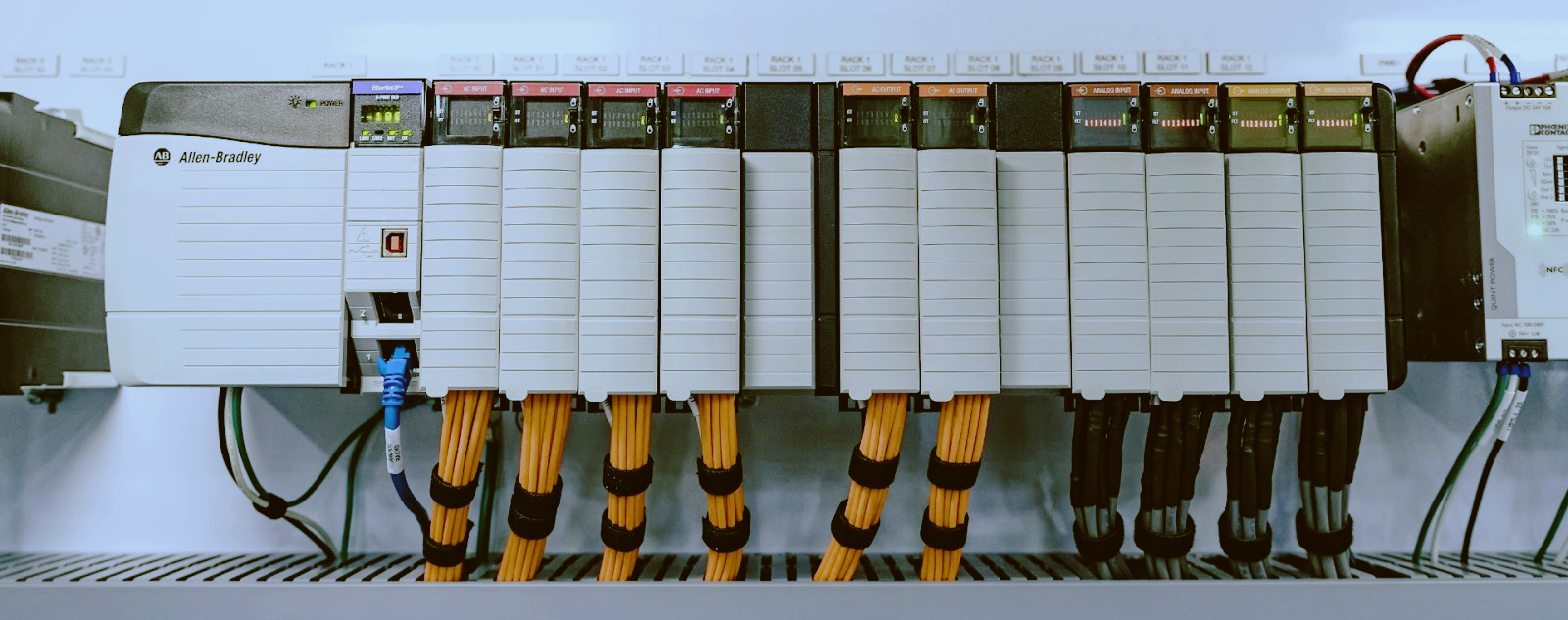
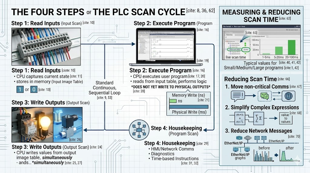
The PLC CPU executes its program in a continuous, sequential loop. Each complete iteration consists of four distinct phases.
The CPU captures the current state of all input modules and stores these values in a dedicated section of memory called the input image table. This happens at the start of every scan cycle.
For digital inputs, the CPU reads a simple 1 (ON) or 0 (OFF) value. For analog inputs, the CPU converts the real-world signal (4-20mA, 0-10V, or temperature sensor data) into a digital value and stores it in memory.
This phase is fast—typically 1 to 10 milliseconds for the entire input scan, depending on the number of input modules and their configuration.
With fresh input data in memory, the CPU executes the user program one instruction at a time. Each instruction is evaluated against the current input image table values, and results are written to the output image table.
This is where ladder logic, function blocks, or structured text instructions actually run. The CPU reads from the input image table, performs logic or arithmetic operations, and stores results in the output image table—but critically, it does not yet write to the physical output modules.
Writing to memory is orders of magnitude faster than communicating with physical I/O modules. Deferring physical output writes until the scan completes ensures all outputs change simultaneously, preventing unstable intermediate states.
The program scan is typically the longest phase. Scan time scales with program size, complexity, and the number of instructions.
After the program scan completes, the CPU writes the values from the output image table to the physical output modules simultaneously. Digital outputs switch on or off. Analog outputs apply their calculated values to the process.
This coordinated write ensures that outputs reflect a consistent snapshot of logic evaluation—no output changes mid-program-scan. The output scan typically takes 1 to 5 milliseconds depending on output module count.
The final phase covers everything else the CPU needs to do between cycles:
· Communicating with HMI panels and other network devices
· Processing time-based instructions (timers, real-time clock)
· Updating diagnostics and fault registers
· Handling communication requests from other PLCs or SCADA systems
Housekeeping time varies based on communication load. A PLC with multiple HMI connections and extensive network messaging may spend significant time here.
Scan time is the total duration of all four phases for one complete cycle. Measured in milliseconds, it directly determines how quickly a PLC can respond to input changes.
Typical values:
· Small program (100-500 instructions): 1-5 ms
· Medium program (1,000-5,000 instructions): 5-20 ms
· Large program (10,000+ instructions): 20-100 ms
The relationship between scan time and machine speed matters. A packaging machine running at 100 packages per minute has 600 milliseconds per cycle. If the PLC scan time consumes 50ms, the machine still has 550ms of available response time—but if scan time reaches 500ms, the machine becomes unresponsive.
For high-speed packaging, bottling, or motion control applications, scan times under 2ms are often required.
A common question: why does the CPU write to a memory table rather than directly to outputs?
The image table approach solves three problems. First, it ensures atomic output updates—every output in a given scan reflects the same logic evaluation. Second, it allows program instructions to read their own output states without creating a feedback loop. Third, it dramatically reduces I/O communication overhead by batching writes.
Without image tables, a single ladder logic scan might trigger dozens of individual output writes at different points during execution, creating unstable machine behavior.
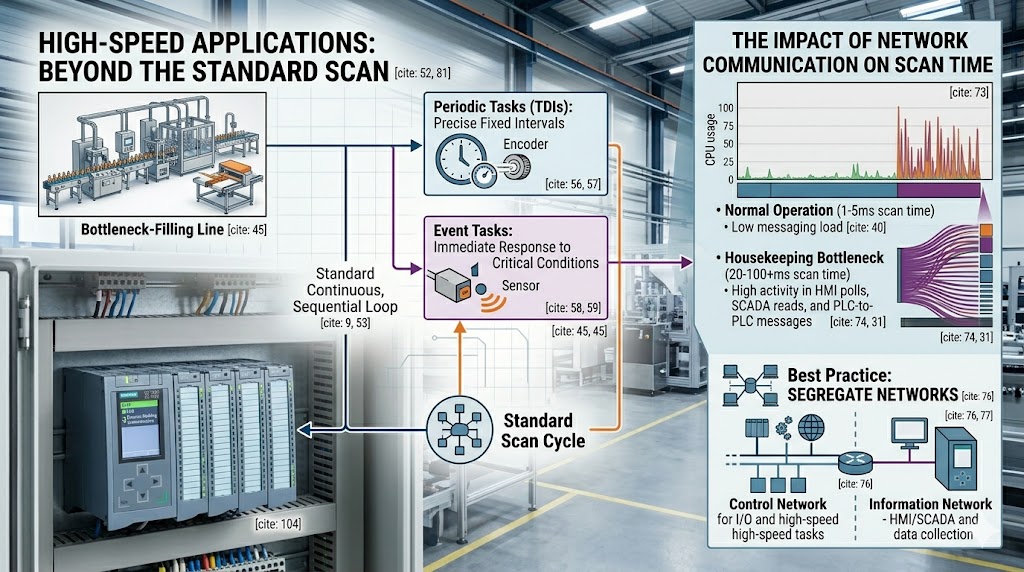
Standard scan cycle execution evaluates every instruction every scan, regardless of whether conditions changed. For most applications this is acceptable, but it wastes CPU time evaluating dormant logic.
Most modern PLCs support interrupt-driven or periodic task execution to handle time-critical events without disrupting the main scan.
Time-derated interrupts (TDIs): Execute a specific routine at a precise interval, independent of the main scan. Used for high-speed counting, encoder processing, or PID control at fixed intervals.
Event-triggered interrupts: Execute when a specific condition occurs—input edge transition, communication event, or fault condition. Critical safety responses often use interrupts to guarantee response time regardless of main scan position.
For Siemens S7-1500, time-critical logic can run in cyclic interrupt organization blocks (OBs) with configurable priorities. Allen Bradley ControlLogix uses periodic and event tasks with configurable rates.
Measuring scan time: Most programming environments display live scan time. In Studio 5000, the Controller Properties > General tab shows execution statistics. In TIA Portal, the Online > Diagnostics menu provides scan time data.
Reducing scan time:
· Move communication instructions (MSG functions) out of the main program scan into periodic tasks
· Simplify complex expressions—replace nested arithmetic with pre-calculated values where possible
· Use direct references instead of copied tags when feasible
· Reduce the number of messages on EtherNet/IP or PROFINET networks
· Consider faster CPU if scan time exceeds application requirements despite optimization
Network communication is the most common cause of unexpected scan time increases. Every HMI poll, every SCADA read, and every PLC-to-PLC message consumes CPU time during the housekeeping phase.
When a PLC must communicate with many devices, the communication load can grow faster than the CPU can handle, causing scan times to increase gradually until a threshold is crossed and machine behavior degrades.
Best practice: segregate time-critical control and network communication onto separate network segments or CPUs. Use one CPU for machine control, another for data collection and reporting.
The PLC scan cycle is the heartbeat of every industrial control system. Understanding its four phases—read inputs, execute program, write outputs, and housekeeping—gives programmers the foundation to write efficient code and troubleshoot responsiveness issues.
Scan time is not just a specification number. It defines the real-time character of your machine. For most applications, a 10-20ms scan time is invisible to operators. For high-speed equipment, 1ms or less separates acceptable performance from catastrophic failure.
Know your process requirements. Measure actual scan time in operation—not just at commissioning—and design your control architecture to maintain that performance throughout the machine lifecycle.
Q: Does a faster CPU always mean faster scan time?
A: Not always. Scan time depends on program complexity, network communication load, and I/O configuration. A faster CPU helps, but eliminating unnecessary instructions and optimizing communication provide larger gains in most applications.
Q: What happens if an input changes state during the program scan?
A: The CPU does not see it until the next scan begins. If an input changes midway through execution and then reverts before the next input scan, the PLC may never detect the event. For events faster than the scan time, use interrupt-driven input processing.
Q: How does online editing affect scan time?
A: When you make program changes while the PLC is running (online edit), the CPU may briefly pause the scan or execute additional overhead to synchronize the new code. Significant online changes can cause temporary scan time increases of 2-5x normal values.
Q: Should I worry about scan time for slow processes like water treatment?
A: For processes changing over seconds or minutes, scan times of 100ms are irrelevant. However, safety-related inputs and alarms should always be processed with minimal delay regardless of process speed. Use interrupts for any input requiring response faster than the normal scan.
Q: Can scan time vary during operation?
A: Yes. Scan time is proportional to program complexity and communication load. A machine idling with no activity may scan faster than the same machine running at full production speed with active HMI interaction and recipe changes.
· [Siemens PLCs](https://www.tztechio.com/siemens) — S7-1500, S7-1200
· [Allen Bradley PLCs](https://www.tztechio.com/allen-bradley) — ControlLogix, CompactLogix
· [Mitsubishi PLCs](https://www.tztechio.com/mitsubishi) — MELSEC iQ-R

Please read on, stay posted, subscribe, and we welcome you to tell us what you think.


Sitemap | Blog | XML | Privacy Policy
In addition, with your permission, we want to place cookies to make your visit anointeraction with slOC more personal. For this we use analytical and advertisingcookies. With these cookies we and third parties can track and collect yourinternet behawior inside and outside super-instrument.com. With this we and third parties adapt super-instrument.com and advertisementsto your interest. By clicking Accept you agree to this. If you decline, we only usethe necessary cookies and you unfortunately will not receive any personalizedcontent. Please visit our Cookie policy for more information or to change yourconsent in the future.
Accept and continue Decline cookies