
How to Choose the Right PLC I/O Module: Digital, Analog, Sinking, and Sourcing Explained
How to choose right PLC I/O module digital analog — that search shows up in every automation forum, every distributor's FAQ, and in the inbox of every applications engineer who has ever picked up the phone. The person asking is usually at the point where they have a PLC platform chosen (or they think they do), and now they need to figure out which I/O cards go in the slots. They know there's a difference between digital and analog. They have heard the words "sinking" and "sourcing" but can't quite hold both definitions in their head at the same time. They are worried about ordering the wrong module and having it show up and not work with their system.
This guide solves that. It walks through what an I/O module actually does, then breaks down digital vs. analog, then explains sinking and sourcing in plain language with real examples, then covers module sizing, and finally ties it all together with platform-specific guidance for Siemens, Allen Bradley, and ABB systems.
A PLC I/O module is the interface between the physical world and the processor. Inputs bring signals into the PLC — a pushbutton state, a pressure transmitter reading, a limit switch trigger. Outputs send signals out to the physical world — a solenoid energizing, a motor starter coil engaging, a valve actuator moving.
The I/O module does the translation. It takes a 24V DC signal from a field device and converts it into a logic-level signal the PLC processor can read. It takes a processor output command and converts it into the voltage and current required to drive a field actuator. Without the right I/O module, the processor is deaf and mute.
Modules come in standard form factors that drop into a PLC rack. The specific module you choose depends on three things: the signal type (digital or analog), the current direction (sinking or sourcing), and the number of points you need.
Digital modules handle on/off signals. The field device is either energized or not energized, open or closed, present or absent. A digital input reads a voltage presence (typically 24V DC for industrial applications). A digital output drives a load on or off.
Common digital input devices:
· Pushbuttons and selector switches
· Limit switches
· Proximity sensors (PNP/NPN)
· Pressure switches
· Relay contacts
Common digital output devices:
· Solenoid valves
· Contactor coils
· Indicator lights
· Horns and beacons
· Motor starter coils
Digital modules are specified by voltage (24V DC, 120V AC, 230V AC are common), by point count (8, 16, 32 are standard), and by the sinking/sourcing characteristic.
Analog modules handle continuous signals — values that vary across a range rather than simply on or off. Where a digital input tells you a tank is full (one bit: full/not full), an analog input tells you the tank level in percentage (multiple bits across a range: 0–100% of the span).
Common analog input signals:
· 4–20 mA (current loop — most common in industrial instrumentation)
· 0–10V DC (voltage signal — common for some transmitters and position sensors)
· 0–5V DC (lower-voltage instrumentation)
· Resistance (RTD) for temperature measurement
· Thermocouple (temperature measurement with cold junction compensation)
Common analog output signals:
· 4–20 mA (most common — drives final control elements like variable frequency drives, control valves)
· 0–10V DC (used for some VFDs and positioners)
Analog modules are specified by signal type (current vs. voltage), resolution (12-bit, 16-bit — higher is more precise), and whether they support multiple input types on the same module.
---
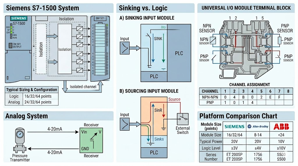
This is the part that trips up most buyers. Sinking and sourcing describe the direction of current flow in a DC circuit. Getting it wrong means your digital input either reads nothing or reads the opposite of what it should.
A sourcing output provides current from the module to the field device. Think of the module as the source of electrons. When the output is active, it connects the positive terminal of its internal supply to the output terminal.
A sourcing input expects current to flow into it from an external source. The input circuit is completed when the sourcing device (a sensor, a switch) provides current.
A sinking output absorbs current from the field device. When active, it connects the output terminal to the negative (ground) side of the circuit.
A sinking input expects current to flow out of it to ground. The external device provides a path to ground, and the input detects the resulting current flow.
The output type of the field device must match the input type of the PLC module, or you need an intermediate relay or interface.
· PNP sensors (sourcing) → connect to sinking inputs, or to sourcing inputs with the polarity reversed
· NPN sensors (sinking) → connect to sourcing inputs, or to sinking inputs with the polarity reversed
The easiest way to check: look at the wiring diagram for the sensor. If the sensor's output wire connects to the PLC input terminal, and the sensor's other wire connects to ground, the sensor is sinking and your input must be sourcing. If the sensor's output wire connects to the PLC input terminal and the sensor's other wire connects to positive, the sensor is sourcing and your input must be sinking.
You cannot simply wire a sourcing sensor into a sourcing input and expect it to work — the two sources push against each other. However, you can use input modules that are specifically designed as "universal" or that have isolated channels, allowing you to mix device types with proper wiring. Always verify the module datasheet before ordering.
Before choosing a module, count the actual field devices in your project. For a small standalone machine, you might have 8 digital inputs and 6 digital outputs. For a more complex line, you might have 32 digital inputs, 16 analog inputs, and 8 analog outputs.
Module sizing rules:
· Digital inputs: Order a module with at least as many points as you have inputs. A 16-point module works for 12 inputs. You cannot exceed the module's point count.
· Digital outputs: Same rule. If you have 10 outputs, a single 8-point module is insufficient — you need a 16-point module or two modules.
· Analog inputs: Each analog input channel is independent. A 4-channel analog input module handles 4 devices. If you have 7 analog transmitters, you need two 4-channel modules (or a single 8-channel module, depending on platform).
· Analog outputs: Same — each channel drives one final control element. A 2-channel module drives two valves.
Add 20% spare capacity. Projects change. Adding a new switch or transmitter after the panel is built is painful and expensive. Specifying a module with a few extra channels costs almost nothing and saves significant rework later.
Platform | Typical Digital Module Sizes | Typical Analog Module Sizes
Siemens S7-1500 | 16, 32, 64 points | 4, 8, 16 channels
Allen Bradley ControlLogix | 8, 16, 32 points | 4, 8 channels
ABB AC500 | 8, 16, 32 points | 4, 8 channels
Siemens uses the ET 200SP and ET 200MP distributed I/O systems alongside onboard I/O on some CPUs. The S7-1500 system uses system-mounted I/O modules (SM modules) that snap onto the CPU or expansion racks.
Key module families:
· SM 521 — Digital input modules (24V DC, 120V AC variants)
· SM 522 — Digital output modules (24V DC relay, solid-state)
· SM 523 — Digital input/output combo modules
· SM 531 — Analog input modules (4–20mA, 0–10V, RTD, thermocouple)
· SM 532 — Analog output modules (4–20mA, 0–10V)
Configuration in TIA Portal requires selecting the correct module type and setting the process image partition and hardware interrupts. Siemens modules are color-coded by type (blue for digital, green for analog), which makes physical identification straightforward on the plant floor.
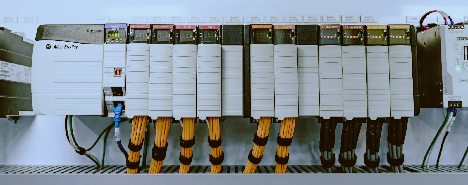
Allen Bradley ControlLogix uses 1756 series I/O modules in a chassis. The platform is highly modular — you can mix digital and analog modules in any slot.
Key module families:
· 1756-IB16 — 16-point 24V DC digital input (sinking)
· 1756-OB16 — 16-point 24V DC digital output (sourcing)
· 1756-IF8 — 8-channel analog input (multiple signal types)
· 1756-OF8 — 8-channel analog output (4–20mA, 0–10V)
Allen Bradley uses the term "sinking" and "sourcing" consistently. The 1756-IB16 is a sinking input. The 1756-OB16 is a sourcing output. Verify polarity before wiring — Allen Bradley 1756 series modules have clear labeling on the front and in the datasheet.
For CompactLogix (5380 and 5480 families), modules are similar but physically smaller (1769 form factor). The 1769-IF8 analog input and 1769-OF4 analog output are common choices.
ABB AC500 uses S500 I/O modules on the CPU rack and distributed I/O (S500 eCo, S500) on fieldbus networks.
Key module families:
· DI524 — 16-point 24V DC digital input
· DO524 — 16-point 24V DC digital output
· AI523 — 4-channel analog input (4–20mA, 0–10V, RTD)
· AO523 — 4-channel analog output (4–20mA, 0–10V)
ABB modules are configured in Automation Builder (the ABB programming environment based on CODESYS). The configuration tool auto-detects many modules when the CPU is online. Channel scaling for analog modules is done in the hardware configuration — always verify the engineering units (PSI, °C, GPM) match the field device span.
---
Q: Can I mix sinking and sourcing inputs on the same module?
A: Some universal-input modules allow you to wire individual channels as either sinking or sourcing, but standard modules typically require all channels to share the same configuration. Check the datasheet. If you need to mix device types, consider using an interface relay or an isolated-input module.
Q: What happens if I use the wrong I/O type — sourcing output into a sourcing input, for example?
A: Nothing works — or worse, it appears to work but behaves in the opposite direction. If you wire a sourcing output directly into a sourcing input, the two voltage sources fight each other. The input may read permanently on or permanently off, depending on the internal circuitry. The correct combination is sourcing output into sinking input (or vice versa) so current flows in one direction.
Q: How many I/O points do I need for a small project?
A: A small standalone machine typically needs 8–16 digital inputs, 6–12 digital outputs, 2–4 analog inputs, and 1–2 analog outputs. Start with a count of your discrete field devices and instrument list, then add 20% for spare capacity. If you are unsure, a distributor's applications engineer can review your instrument list and recommend a module configuration.
Q: My analog input reads a value when no sensor is connected. Is the module broken?
A: No — unconnected analog input channels can read random noise (typically a small non-zero value). This is normal. The channel only becomes meaningful when the sensor (transmitter) is wired and the loop is energized (for 4–20mA devices). Always verify that the 24V DC loop power is present at the channel terminal before troubleshooting a reading.
Q: Can I replace a 24V DC digital output module with a 120V AC module on the same system?
A: Only if the field devices are also rated for the new voltage. You cannot drive a 24V DC solenoid with a 120V AC output module. Changing voltage classes requires changing the field devices, the wiring, and potentially the module. Always match the module voltage to the device voltage.
Q: What is channel isolation and why does it matter?
A: Isolated channels have individual circuit isolation between each input or output channel. Non-isolated modules share a common ground across all channels. Isolation matters when you have field devices on different voltage sources or when you need to protect the system from ground loops and voltage spikes on individual channels. For critical analog measurements (flow transmitters, pressure transmitters), isolated modules provide cleaner signals and better accuracy.
TZ Tech is a professional supplier for industrial automation and electrical parts, as well as some instrumentation, telecommunication parts. We mostly sell the ready stock of distributor, with competitive price and short lead time. Even discontinued parts we may also can supply as we have a large inventory here.
We understand what you concern, so we will ensure the quality. We strictly screen the components you require, so you don’t need worry about any quality issues with the goods you receive. For specialized parts that have long since been discontinued, we will sincerely inform you the actual condition of the goods. All brand new parts we will support 1 year warranty.
If you need any related parts, please feel free to send an inquiry. Our staff will support quick response within 6 hours. (except weekend here)


Please read on, stay posted, subscribe, and we welcome you to tell us what you think.


Sitemap | Blog | XML | Privacy Policy
In addition, with your permission, we want to place cookies to make your visit anointeraction with slOC more personal. For this we use analytical and advertisingcookies. With these cookies we and third parties can track and collect yourinternet behawior inside and outside super-instrument.com. With this we and third parties adapt super-instrument.com and advertisementsto your interest. By clicking Accept you agree to this. If you decline, we only usethe necessary cookies and you unfortunately will not receive any personalizedcontent. Please visit our Cookie policy for more information or to change yourconsent in the future.
Accept and continue Decline cookies