
Danfoss VFD-PLC Communication: Setup Guide for Common Protocols
You've wired everything correctly. The Danfoss VLT drive powers up, the motor spins, and the PLC is online. But the second you send a write command over the fieldbus, you get a comm fault — or worse, the drive ignores you completely. I've been there. Parameter 8‑30 shows "No Message," the green Fieldbus LED blinks an angry pattern, and the production manager is staring over your shoulder. This article is the cheat sheet I wish I'd had on my first dozen Danfoss integrations. We'll cover the four major protocols — PROFIBUS, PROFINET, EtherNet/IP, and Modbus RTU — with the exact parameter numbers, PCD mappings, and troubleshooting steps you need to get data moving reliably.

Danfoss has produced several generations of VFDs under the VLT brand. The most common models you'll encounter in industrial settings are the VLT Micro Drive FC 51, VLT AutomationDrive FC 302, VLT AQUA Drive FC 202, and the newer VLT Midi Drive FC 280 and iC7 Series. For PLC integration, the FC 302 and FC 202 are the workhorses — they support the full suite of communication option cards and have the richest parameter sets.
Protocol | Typical Use Case | Option Card Required?
Modbus RTU (RS‑485) | Legacy plants, simple SCADA, small PLCs | No — built into standard drives
PROFIBUS DP | Siemens S7‑300/400, older plants | VLT PROFIBUS DP MCA 101
PROFINET | Siemens S7‑1200/1500, modern lines | VLT PROFINET MCA 120 or MCA 121
EtherNet/IP | Allen‑Bradley CompactLogix / ControlLogix | VLT EtherNet/IP MCA 121
Key point: If your drive is an FC 51, you're limited to Modbus RTU via the built‑in RS‑485 terminals (68, 69, 61). For the FC 302/202/280, you can add any of the option cards above. The iC7 series has integrated multi‑protocol Ethernet — no card required.
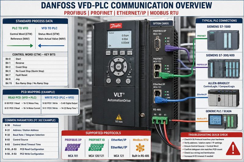
Every Danfoss fieldbus implementation is built on the same foundation: a Control Word (CTW), a Reference / Main Actual Value (MAV), and a set of Process Data (PCD) words. You don't need to memorize every bit in the CTW — the critical ones are:
· Bit 0: Start command
· Bit 1: Reverse
· Bit 2: Coast stop
· Bit 3: No coast stop (quick stop)
· Bit 7: Reset fault
· Bit 8: Jog
· Bit 15: Bus ramp stop / no ramp stop selection
The Status Word (STW) mirrors these: Bit 0 = Ready, Bit 1 = Ready to Run, Bit 2 = Running, Bit 3 = Running at Reference, Bit 7 = Fault, etc. Get comfortable with these — they're identical across all protocols.
Modbus RTU is the simplest and most forgiving. It's built into every VLT drive on terminals 68 (TX+/RX+) , 69 (TX-/RX-) , and 61 (common) .
Parameter checklist for FC 302:
· 8‑30 Protocol = `Modbus RTU`
· 8‑31 Address = set your bus address (1‑247)
· 8‑32 Baud Rate = match your master (9600, 19200, 38400)
· 8‑33 Parity / Stop Bits = `Even, 1 Stop` (common) or `No Parity, 2 Stop`
· 8‑35 Minimum Response Delay = 10 ms (start here; increase if collisions occur)
· 8‑36 Maximum Response Delay = 100 ms
Writing to the control word: Modbus holding register address 0x2000 (dec 8192). Reference value goes into 0x2002 (dec 8194). Reading actual speed? Register 0x2100 (dec 8448) for the status word and 0x2102 (dec 8450) for the main actual value.
Common mistake: You send 0x047F to register 0x2000 expecting the drive to run, and nothing happens. Check 8‑30 — if it's set to FC Profile instead of Modbus RTU, the drive won't interpret the control word correctly. Also verify 8‑50 Coasting Select isn't overriding your start command.
PROFIBUS gets a bad rap for being fiddly, but once the GSD file is loaded and the baud rate locks, it's rock solid.
Hardware:
· VLT PROFIBUS DP MCA 101 option card
· BUS terminals: A‑line (red), B‑line (green), shield connected at both ends
· Termination resistors ON at the two physical ends of the segment
Parameter setup:
· 8‑30 Protocol = `PROFIBUS DP`
· 8‑31 Station Address = match your HW DIP switches (or parameter setting if software addressing is enabled)
· 8‑32 Telegram Selection = `Standard Telegram 1` (2 words: CTW+MAV) or `Standard Telegram 20` (6 words: CTW+MAZ+4 PCD). For most speed‑controlled applications, Telegram 1 is enough.
· 8‑02 Control Source = `Digital Input and Control Word`
· 8‑03 Control Word Timeout Time = 1.0 s (if no message in 1 second, trip)
GSD file: Download DANF0653.GSD or DANF06B3.GSD from Danfoss's site and import into TIA Portal or Step 7. The slot configuration is straightforward — slot 1 = control word, slot 2 = reference, slots 3‑6 = PCD.
PCD mapping (Telegram 20): If you need to read motor current (parameter 16‑14) or DC link voltage (parameter 14‑30), map them via 8‑50* to 8‑53* (for read PCDs) and 9‑50* to 9‑53* (for write PCDs). Example:
· 8‑50 PCD 1 Read = `16‑14 Motor Current`
· 8‑51 PCD 2 Read = `14‑30 DC Link Voltage`
VLT PROFINET MCA 120 (older) or MCA 121 (current). The process is nearly identical to PROFIBUS conceptually, but simpler because PROFINET handles addressing automatically via DCP.
Parameter setup:
· 8‑30 Protocol = `PROFINET IO`
· 8‑70 IO‑Cycle Time = 4 ms (default; lower = faster but more CPU load)
· 8‑72 PROFINET Station Name = set this via the VLT Memory Card tool or the drive keypad (or use DCP tool like PRONETA)
· 8‑02 Control Source = `Control Word`
GSDML file: Import GSDML‑V2.33‑Danfoss‑MCA121‑2023xxxx.xml (version varies). The standard telegram sizes match PROFIBUS: Telegram 1 (2 words), Telegram 20 (6 words), Telegram 21 (10 words), etc.
PROFINET-specific tips:
1. Station Name must match exactly — case-sensitive. If the PLC can't find the drive, use Siemens PRONETA to scan the network and rename the device.
2. IO‑Cycle Time: Don't go below 2 ms unless you've verified the PLC's DR cycle can handle it. I've seen TIA Portal reject anything under 1 ms on older CPUs.
3. Watchdog: Parameter 8-03 still applies. Set to 2x your IO‑Cycle Time.
For Allen‑Bradley users, the VLT EtherNet/IP MCA 121 card makes the drive appear as a standard CIP device. You'll need the EDS file from Danfoss.
Parameter setup:
· 8‑30 Protocol = `EtherNet/IP`
· 8‑70 IO‑Cycle Time = RPI setting in the PLC (default 10 ms is fine)
· 8‑72 IP Address Assignment = `DHCP`, `Static`, or `BootP` (match your plant's IP scheme)
· 8‑74 Subnet Mask and 8‑75 Default Gateway — set if static
· 8‑02 Control Source = `Control Word`
Studio 5000 / Logix Designer setup:
4. Download the EDS file from Danfoss and register it via `Tools > EDS Hardware Installation Tool`.
5. Add the drive to the IO tree under your Ethernet bridge. The default assembly instances are:
· Output Assembly (PLC → Drive): Instance 101 (4 words: CTW + Ref + 2 PCD)
· Input Assembly (Drive → PLC): Instance 102 (8 words: STW + MAV + 6 PCD)
6. Map the data to controller tags. I typically create a UDT with `Drive_CTW`, `Drive_Ref`, `Drive_STW`, and `Drive_MAV`.
Common issue: If the drive shows "No Connection" in the module status, check that the RPI in the PLC matches 8‑70. Also verify the IP address isn't duplicated — ping it from a laptop before commissioning.
This is where most people get stuck. The PCD mapping lets you read or write any drive parameter over the fieldbus beyond the standard CTW/MAV.
Read PCDs (drive → PLC): 8‑50 through 8‑53 (up to 4 read PCDs in Telegram 20). Each parameter slot expects the parameter number of the data you want to read.
Write PCDs (PLC → drive): 9‑50 through 9‑53. Want the PLC to set the digital output terminal? Map 5‑40 Function of Digital Out to a write PCD.
Example: You want to read motor frequency (16‑12) and motor current (16‑14) back from the drive:
`
8‑50 PCD 1 Read Configuration = 16‑12 motor frequency [Hz]
8‑51 PCD 2 Read Configuration = 16‑14 motor current [A]
`
Now the PLC reads STW + MAV + PCD1 + PCD2. The PCD values appear in the telegrams after the MAV slot. Scaling is handled by the parameter's defined unit — 16‑12 is in 0.01 Hz, 16‑14 is in 0.1 A.
Fault / Symptom | Likely Cause | Fix
Alarm 34 / Bus Fault | No valid fieldbus message received within 8‑03 timeout | Check cable, master state, and that 8‑30 matches your hardware
Drive doesn't start (no rotation) | Control Word bits not set correctly, or 5‑12/5-13 terminal conflicts | Set 8‑02 Control Source to `Control Word` exclusively; disable any digital input start commands
Alarm 22 / Hardware fault | PROFIBUS: wrong baud rate or duplicate station address | Force baud via GSD file; verify address uniqueness
PROFINET device not found | Station Name mismatch or IP conflict | Use PRONETA to scan and reassign; reboot the drive after renaming
EtherNet/IP "No Connection" | RPI mismatch or EDS file version | Match 8‑70 RPI to PLC connection RPI; download latest EDS from Danfoss
I've seen engineers spend hours troubleshooting because they entered 8‑50 PCD 1 Read Configuration as 16‑12 but forgot to set 8‑32 Telegram Selection to Standard Telegram 20 (or higher). With Telegram 1, the drive only sends CTW+MAV — any PCD slots are simply ignored. Always verify your telegram size matches your PCD count.
For RS‑485 (Modbus RTU) , the built‑in termination resistor is enabled via 8‑36 in some drive variants, or by a physical DIP switch on the control card. For PROFIBUS, use the DIP switches on the MCA 101 card — position ON for the end devices. For PROFINET and EtherNet/IP, no bus termination is needed (standard Ethernet wiring rules apply: star topology, cable run < 100 m per segment).
At TZTech.io, we stock a wide range of Danfoss VFD units and communication option cards, including hard‑to‑find legacy variants.
Part Number | Description | Typical Lead Time
VLT FC 302 (various kW) | AutomationDrive, 0.25–75 kW | In stock
VLT FC 202 (various kW) | AQUA Drive, pump/fan applications | In stock
MCA 101 | PROFIBUS DP option card | 3–5 business days
MCA 120 | PROFINET option card (older) | Limited stock
MCA 121 | PROFINET / EtherNet/IP option card (current) | In stock
VLT 2800 | Legacy VFD (discontinued — check availability) | Contact us
All parts are tested before shipping. We ship globally to the Middle East, Americas, and Europe. Need a replacement Danfoss VFD for a line‑down situation? Browse our Danfoss inventory or check our full VFD selection. For complete PLC integration packages, see our PLC spare parts section.
No — the built‑in RS‑485 port and an option card share the same internal communication bus on most FC 302 drives. Only one fieldbus protocol can be active at a time. Set 8‑30 to the protocol you're using.
Alarm 34 is a bus timeout. Check 8‑03 Control Word Timeout Time — if it's set lower than your PLC's update rate, the drive trips. Increase it to 2–5 seconds for testing, then dial it back to 2x your bus cycle time in production.
Yes, if you want to monitor the drive or see the last fault code after a power loss. Wire 24 V DC to terminals 35 (+) and 39 (-) on the FC 302 control card. Without it, the option card loses power with the mains.
8‑02 Control Source defaults to Digital Only on many FC 302 drives. Change it to Control Word Only to force the drive to accept start/stop commands exclusively from the fieldbus. If you need both (local pushbutton + bus), set it to Digital Input and Control Word and configure the digital inputs for "Bus Start" in 5‑12.
Standard PROFINET cable: 100 m per segment between switches. If your drive is farther from the switch than that, install a PROFINET repeater or a media converter (fiber optic). For Modbus RTU, max is 1200 m at 9600 baud — drop to 400 m at 38400 baud.
The VLT 5000 uses the Profibus DP V1 card (part no. 176Fxxxx), and the VLT 2800 uses the SI‑P or SI‑M cards. These are discontinued but we occasionally have tested used units in stock. Contact us with your exact model number and we'll check availability.
---
*Need a replacement Danfoss VFD or comm card fast? Shop Danfoss VFD spare parts at TZTech.io — tested, shipped globally, and backed by real engineers who know the hardware.*

Please read on, stay posted, subscribe, and we welcome you to tell us what you think.


Sitemap | Blog | XML | Privacy Policy
In addition, with your permission, we want to place cookies to make your visit anointeraction with slOC more personal. For this we use analytical and advertisingcookies. With these cookies we and third parties can track and collect yourinternet behawior inside and outside super-instrument.com. With this we and third parties adapt super-instrument.com and advertisementsto your interest. By clicking Accept you agree to this. If you decline, we only usethe necessary cookies and you unfortunately will not receive any personalizedcontent. Please visit our Cookie policy for more information or to change yourconsent in the future.
Accept and continue Decline cookies