PLC ENGINEERING

Blog

Home

Blog

  • Why Do Bently Nevada 3500 Modules Keep Failing? The 6 Problems Every Technician Hits
    Why Do Bently Nevada 3500 Modules Keep Failing? The 6 Problems Every Technician Hits May 18, 2026
      URL Slug: bently-nevada-3500-troubleshooting-guide-common-faults   The Problem Nobody Talks About Bently Nevada 3500 common faults troubleshooting keeps plant floor technicians up at night. You pull a shift at a Saudi Aramco gas processing facility or a UAE refinery on the Gulf Coast, and that 3500 rack starts throwing channel faults the moment you think everything is stable. Prox probe wear kills accuracy. Power supply modules drop out under load. Software config mistakes take down an entire machinery protection system trip chain. If you run Bently Nevada equipment in any serious industrial setting, at least one of these six failures has hit your rack already — and if it hasn't, the day it does, you need to know exactly what to do. This guide covers the six most frequent 3500 module failures: what causes them, how to diagnose them, and how to fix them right the first time. We focus on the 3500/22 Transient Data Interface, 3500/40 Machinery Protection Monitor, and 3500/15 Power Supply modules because those three account for the bulk of downtime calls in oil and gas, petrochemical, and turbine applications across the Middle East and North America.   What Is the Bently Nevada 3500 System? The Bently Nevada 3500 is a rack-based machinery protection system designed for continuous online monitoring of turbines, compressors, pumps, and other rotating equipment. Unlike simple alarm units, the 3500 provides both protection (trip functions) and monitoring (trend data, waveform capture) in a single architecture. A typical 3500 rack holds: · 3500/15 Power Supply Modules (primary and redundant) · 3500/22 Transient Data Interface (TDI) for communication · 3500/40 (or 3500/44, 3500/45) Machinery Protection Monitors with specific channel counts · Various I/O modules for prox probes, velocity sensors, and ROTA (Rotating Termal Analyzer) inputs The rack communicates via Ethernet or serial to a host system, and the 3500 software (System 1 or 3500 Fleet software) handles configuration, alarm routing, and data logging. The problem: when any module in that rack fails or misbehaves, the root cause is almost never obvious — and the fix requires understanding how the modules interact.   The 6 Most Common Bently Nevada 3500 Faults Fault 1: Prox Probe Wear and Channel Faults Symptoms: Intermittent channel fault LEDs on the 3500/40 monitor. Alarm trips with no corresponding machinery event. Bad channel readings that drift over weeks. Cause: Prox probe (inductive eddy current) sensors have a finite life. The probe tip wears against the shaft runout surface, the calibration gap shifts, and the 3500 channel goes into fault when the gap voltage exceeds the configured window. In high-temperature environments like gas turbine bearing housings, probe lifespan drops significantly. Fix: Check the channel gap voltage in 3500 Fleet software — each channel displays a gap voltage in volts. A healthy reading sits within ±2V of the calibrated value. If it's drifting, replace the probe. Calibration a new probe requires the machinery to be offline and the shaft centered. Document the new gap voltage before returning to service. Regional note: At Saudi Arabia oil & gas facilities, probe replacement cycles run 12–18 months in high-vibration turbomachinery. UAE refinery operators report shorter cycles (9–14 months) due to higher ambient temperatures in compressor houses. --- Fault 2: Machinery Protection System (MPS) Trips — Unexpected Symptoms: The 3500 rack trips the machine unexpectedly. The trip cause appears in the event log but the alarm seems disproportionate to the machinery condition. Cause: Incorrect alarm setpoints. A common mistake: alarm levels set too close to the trip setpoint, or the trip relay configuration (normally open vs. normally closed) mismatched with the host logic. Another cause: test function accidentally activated during online operation, triggering a real trip. Fix: Review the 3500/22 configuration in System 1. Verify the alarm and trip setpoints against the original machinery vendor specifications. Check relay output configuration — the 3500/22 has relay outputs that can be mapped to alarm or trip functions. If the trip was triggered by a test function, reset the system and review the event log for the test timestamp. Always perform test functions with the machine in a pre-agreed state and the host operator informed. --- Fault 3: Rack Communication Errors Symptoms: 3500/22 shows a communication fault or the host system loses contact with the rack. The LED on the 3500/22 may show a steady red or amber pattern. Cause: The Ethernet or serial link between the 3500/22 and the host has failed, or the internal rack communication (ribbon cable or backplane) is disrupted. The 3500/22 can also lose communication if multiple racks are networked and an IP address conflict occurs. Fix: First, check physical connections — Ethernet cable seating, serial cable integrity. Verify the 3500/22 IP address against the host configuration. A power cycle of the entire rack (remove and reapply power to 3500/15 modules) often restores communication. If the 3500/22 itself has failed, it must be replaced and reconfigured with the correct rack address and channel configuration. Always back up the 3500 configuration (via System 1) before replacing any module. --- Fault 4: Channel Calibration Drift Symptoms: A channel that previously read correctly now shows a persistent offset from expected values. The machinery is healthy but the 3500 channel indicates a warning or alarm. Cause: The 3500/40 monitor uses software-based channel calibration. Over time, the calibration constants can drift, particularly in monitors that have been running for years without a firmware update. The issue is exacerbated in environments with high vibration or temperature cycling. Fix: Perform a channel calibration using the 3500 Fleet software calibration wizard. This requires a known calibration signal source (a calibrator capable of outputting the sensor's rated range — typically 200 mV/mil for proximity probes). Follow the on-screen wizard, save the calibration to the monitor, and verify the channel reading. If drift persists after recalibration, the monitor module may be failing and should be replaced. --- Fault 5: Power Supply Failures Symptoms: 3500/15 module shows a fault LED, or the entire rack goes dark. Redundant power supply does not take over cleanly during a failure event. Cause: The 3500/15 is a switching power supply. In environments with unstable mains power or significant electrical noise (common near large motors or variable frequency drives), the supply can fail. Aging capacitors in older 3500/15 units are a common failure point. If the redundant supply fails to pick up load, the issue is often in the power distribution wiring or the supply's load-sharing circuit. Fix: Replace the failed 3500/15 with a known-good unit. Before replacement, verify input voltage at the supply terminals — nominal 24V DC or 115/230V AC depending on the module variant. After replacement, the new supply should immediately show a green LED. Test the redundant supply by temporarily removing the primary — the rack should stay powered and the event log should record the switchover. If the redundant supply does not take over, check the load-sharing wiring between the two 3500/15 modules. --- Fault 6: Software Configuration Mistakes Symptoms: Channels map to the wrong inputs. Alarms trigger on inactive channels. The 3500/22 shows correct data but the host system receives garbage. The rack functions correctly in standalone mode but fails when integrated with the plant DCS. Cause: Configuration errors after a firmware update, module replacement, or a change to the System 1 project file. The 3500 architecture stores channel configuration in each monitor module, not centrally — so replacing a 3500/40 without loading the correct configuration file results in a blank or miswired monitor. Another common mistake: incorrect channel normalization (scaling) after replacing a prox probe with a different model. Fix: Always back up the full rack configuration (System 1 → Save As) before any module swap. When replacing a monitor, use the "Upload from Monitor" function to pull the existing configuration, then apply it to the new module. For integration with a DCS or SCADA host, verify the Modbus register map or Ethernet/IP explicit message configuration matches the 3500 channel layout. A mismatch in byte order (big-endian vs. little-endian) is a frequent culprit in Modbus integrations. Bently Nevada 3500 vs 3300: Which System Should You Use? Feature | Bently Nevada 3500 | Bently Nevada 3300 Architecture | Rack-based, modular | Rack-based, modular Channel Density | Up to 16 channels per monitor module | Up to 8 channels per module Communication | Ethernet, Modbus, serial | Serial, limited Ethernet Protection Capability | Full trip and monitoring | Monitoring primarily Firmware Updates | Field-upgradeable | Limited Redundant Power Supply | Yes (3500/15) | Optional Typical Application | Turbines, compressors, critical machinery | Pumps, fans, general-purpose monitoring Price Range (used) | Higher | Lower Regional Availability | Widely stocked in ME distributors | More common in North America Recommendation: Use 3500 for any application where machinery protection (trip functionality) is required — particularly turbines, compressors, and large reciprocating machines in oil & gas. Use 3300 for auxiliary monitoring where the full trip function is handled by a separate protection system. In Saudi Arabia and UAE, 3500 is the standard for new installations; 3300 units are typically found in older plants or secondary monitoring roles. --- Regional Notes: Where These Faults Hit Hardest Saudi Arabia (Saudi Aramco, SABIC): Prox probe wear and MPS trips dominate service calls. Saudi facilities run 3500 racks at very high utilization rates on gas injection compressors. Power supply failures are also common due to the harsh inland climate (high temperatures, sand intrusion). UAE (ADNOC, Dubai refineries): Channel calibration drift is the most reported issue, attributed to rapid temperature cycling in coastal facilities where seawater cooling creates condensation. 3500/22 communication errors are also frequent due to network integration complexity with multiple DCS platforms. US Gulf Coast: Software configuration mistakes lead the failure list, driven by the high number of third-party integrators and frequent module swaps during turnaround maintenance. ROTA-related faults (rotating thermal analyzer inputs on 3500/45 modules) are more common here due to the large installed base of gas turbines in combined-cycle plants. --- FAQ Q: How often should prox probes be replaced on a Bently Nevada 3500 system? A: Typical probe replacement intervals run 12–24 months depending on the application. High-temperature, high-vibration environments (gas turbines, compressors) require replacement at the shorter end. Always gap-check after replacement and document the new baseline voltage. Q: Can I replace a 3500/40 monitor without taking the machinery offline? A: The monitor module can be swapped with the machine running as long as the specific channel being replaced is not in a trip-active state and the redundant protection (if configured) is healthy. However, the replacement monitor must be pre-configured with the correct channel settings before installation. Never remove a monitor while its channel is actively in alarm. Q: What causes a 3500/22 to lose communication with the host? A: The most common causes are physical connection failure (Ethernet cable, serial cable), IP address conflict on a networked rack, or power supply issues affecting the 3500/22 specifically. A power cycle of the rack usually restores communication. If the 3500/22 itself has failed, it must be replaced and reconfigured. Q: My 3500 rack keeps tripping unexpectedly. What's the most likely cause? A: Check the alarm setpoints first. If alarm levels are set too close to trip setpoints, normal operational vibration can trigger a trip. Also verify that the relay output configuration matches the host system's expected logic (normally open vs. normally closed). Review the event log — it will record the exact channel, value, and timestamp of the trip-triggering event. Q: How do I know if my 3500/15 power supply is failing? A: A failing 3500/15 typically shows a fault LED (amber or red) before complete failure. You may also notice intermittent communication drops or channel faults that coincide with mains supply disturbances. Replace at the first sign of a fault LED — do not wait for complete failure, as a dead primary with a failed redundant supply will take the entire rack offline. Q: Is the Bently Nevada 3500 still a current product? A: Bently Nevada continues to sell and support the 3500 system, though the product line has been supplemented by newer platforms. The 3500 remains the standard for critical machinery protection in oil & gas, power generation, and petrochemical industries globally. However, some legacy modules (particularly older 3500/22 variants) have reached end-of-life — check with Honeywell (parent company of Bently Nevada) for current availability. --- For Bently Nevada products, visit tztechio.com/bently-nevada. For PLC and automation solutions, see tztechio.com/plc.   TZ Tech is a professional supplier for industrial automation and electrical parts, as well as some instrumentation, telecommunication parts. We mostly sell the ready stock of distributor, with competitive price and short lead time. Even discontinued parts we may also can supply as we have a large inventory here.    We understand what you concern, so we will ensure the quality. We strictly screen the components you require, so you don’t need worry about any quality issues with the goods you receive. For specialized parts that have long since been discontinued, we will sincerely inform you the actual condition of the goods. All brand new parts we will support 1 year warranty.     If you need any related parts, please feel free to send an inquiry. Our staff will support quick response within 6 hours. (except weekend here)
  • What is a PLC Scan Cycle? How PLCs Execute Programs
    What is a PLC Scan Cycle? How PLCs Execute Programs May 12, 2026
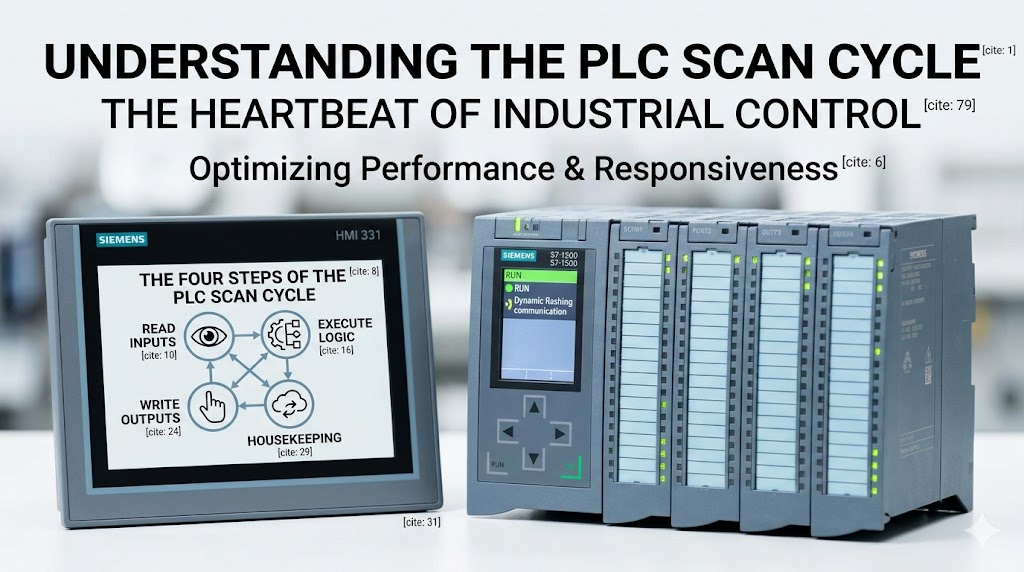
    Introduction Every PLC runs the same fundamental loop from the moment it powers on—read inputs, execute logic, write outputs, repeat. This cycle, called the scan cycle, determines how responsive a PLC is to real-world events and sets the performance ceiling for any controlled process. Understanding scan cycle mechanics helps programmers optimize code, troubleshoot responsiveness issues, and select the right CPU for demanding applications. This guide explains exactly how the scan cycle works and what factors affect it. The Four Steps of the PLC Scan Cycle The PLC CPU executes its program in a continuous, sequential loop. Each complete iteration consists of four distinct phases. Step 1: Read Inputs (Input Scan) The CPU captures the current state of all input modules and stores these values in a dedicated section of memory called the input image table. This happens at the start of every scan cycle. For digital inputs, the CPU reads a simple 1 (ON) or 0 (OFF) value. For analog inputs, the CPU converts the real-world signal (4-20mA, 0-10V, or temperature sensor data) into a digital value and stores it in memory. This phase is fast—typically 1 to 10 milliseconds for the entire input scan, depending on the number of input modules and their configuration. Step 2: Execute Program (Program Scan) With fresh input data in memory, the CPU executes the user program one instruction at a time. Each instruction is evaluated against the current input image table values, and results are written to the output image table. This is where ladder logic, function blocks, or structured text instructions actually run. The CPU reads from the input image table, performs logic or arithmetic operations, and stores results in the output image table—but critically, it does not yet write to the physical output modules. Writing to memory is orders of magnitude faster than communicating with physical I/O modules. Deferring physical output writes until the scan completes ensures all outputs change simultaneously, preventing unstable intermediate states. The program scan is typically the longest phase. Scan time scales with program size, complexity, and the number of instructions. Step 3: Write Outputs (Output Scan) After the program scan completes, the CPU writes the values from the output image table to the physical output modules simultaneously. Digital outputs switch on or off. Analog outputs apply their calculated values to the process. This coordinated write ensures that outputs reflect a consistent snapshot of logic evaluation—no output changes mid-program-scan. The output scan typically takes 1 to 5 milliseconds depending on output module count. Step 4: Housekeeping The final phase covers everything else the CPU needs to do between cycles: · Communicating with HMI panels and other network devices · Processing time-based instructions (timers, real-time clock) · Updating diagnostics and fault registers · Handling communication requests from other PLCs or SCADA systems Housekeeping time varies based on communication load. A PLC with multiple HMI connections and extensive network messaging may spend significant time here. Understanding Scan Time Scan time is the total duration of all four phases for one complete cycle. Measured in milliseconds, it directly determines how quickly a PLC can respond to input changes. Typical values: · Small program (100-500 instructions): 1-5 ms · Medium program (1,000-5,000 instructions): 5-20 ms · Large program (10,000+ instructions): 20-100 ms The relationship between scan time and machine speed matters. A packaging machine running at 100 packages per minute has 600 milliseconds per cycle. If the PLC scan time consumes 50ms, the machine still has 550ms of available response time—but if scan time reaches 500ms, the machine becomes unresponsive. For high-speed packaging, bottling, or motion control applications, scan times under 2ms are often required. Why Output Image Tables Exist A common question: why does the CPU write to a memory table rather than directly to outputs? The image table approach solves three problems. First, it ensures atomic output updates—every output in a given scan reflects the same logic evaluation. Second, it allows program instructions to read their own output states without creating a feedback loop. Third, it dramatically reduces I/O communication overhead by batching writes. Without image tables, a single ladder logic scan might trigger dozens of individual output writes at different points during execution, creating unstable machine behavior. Event-Driven Execution: Interrupts and Periodic Tasks Standard scan cycle execution evaluates every instruction every scan, regardless of whether conditions changed. For most applications this is acceptable, but it wastes CPU time evaluating dormant logic. Most modern PLCs support interrupt-driven or periodic task execution to handle time-critical events without disrupting the main scan. Time-derated interrupts (TDIs): Execute a specific routine at a precise interval, independent of the main scan. Used for high-speed counting, encoder processing, or PID control at fixed intervals. Event-triggered interrupts: Execute when a specific condition occurs—input edge transition, communication event, or fault condition. Critical safety responses often use interrupts to guarantee response time regardless of main scan position. For Siemens S7-1500, time-critical logic can run in cyclic interrupt organization blocks (OBs) with configurable priorities. Allen Bradley ControlLogix uses periodic and event tasks with configurable rates. How to Measure and Reduce Scan Time Measuring scan time: Most programming environments display live scan time. In Studio 5000, the Controller Properties > General tab shows execution statistics. In TIA Portal, the Online > Diagnostics menu provides scan time data. Reducing scan time: · Move communication instructions (MSG functions) out of the main program scan into periodic tasks · Simplify complex expressions—replace nested arithmetic with pre-calculated values where possible · Use direct references instead of copied tags when feasible · Reduce the number of messages on EtherNet/IP or PROFINET networks · Consider faster CPU if scan time exceeds application requirements despite optimization The Impact of Network Communication on Scan Time Network communication is the most common cause of unexpected scan time increases. Every HMI poll, every SCADA read, and every PLC-to-PLC message consumes CPU time during the housekeeping phase. When a PLC must communicate with many devices, the communication load can grow faster than the CPU can handle, causing scan times to increase gradually until a threshold is crossed and machine behavior degrades. Best practice: segregate time-critical control and network communication onto separate network segments or CPUs. Use one CPU for machine control, another for data collection and reporting. Conclusion The PLC scan cycle is the heartbeat of every industrial control system. Understanding its four phases—read inputs, execute program, write outputs, and housekeeping—gives programmers the foundation to write efficient code and troubleshoot responsiveness issues. Scan time is not just a specification number. It defines the real-time character of your machine. For most applications, a 10-20ms scan time is invisible to operators. For high-speed equipment, 1ms or less separates acceptable performance from catastrophic failure. Know your process requirements. Measure actual scan time in operation—not just at commissioning—and design your control architecture to maintain that performance throughout the machine lifecycle. Frequently Asked Questions Q: Does a faster CPU always mean faster scan time? A: Not always. Scan time depends on program complexity, network communication load, and I/O configuration. A faster CPU helps, but eliminating unnecessary instructions and optimizing communication provide larger gains in most applications. Q: What happens if an input changes state during the program scan? A: The CPU does not see it until the next scan begins. If an input changes midway through execution and then reverts before the next input scan, the PLC may never detect the event. For events faster than the scan time, use interrupt-driven input processing. Q: How does online editing affect scan time? A: When you make program changes while the PLC is running (online edit), the CPU may briefly pause the scan or execute additional overhead to synchronize the new code. Significant online changes can cause temporary scan time increases of 2-5x normal values. Q: Should I worry about scan time for slow processes like water treatment? A: For processes changing over seconds or minutes, scan times of 100ms are irrelevant. However, safety-related inputs and alarms should always be processed with minimal delay regardless of process speed. Use interrupts for any input requiring response faster than the normal scan. Q: Can scan time vary during operation? A: Yes. Scan time is proportional to program complexity and communication load. A machine idling with no activity may scan faster than the same machine running at full production speed with active HMI interaction and recipe changes. Related Products · [Siemens PLCs](https://www.tztechio.com/siemens) — S7-1500, S7-1200 · [Allen Bradley PLCs](https://www.tztechio.com/allen-bradley) — ControlLogix, CompactLogix · [Mitsubishi PLCs](https://www.tztechio.com/mitsubishi) — MELSEC iQ-R
  • The SIMATIC S5 Is Still Running Your Plant: A 6ES5 Field Guide for 2026
    The SIMATIC S5 Is Still Running Your Plant: A 6ES5 Field Guide for 2026 Aug 11, 2026
    The phone rang at 2:37 in the morning. I knew it was a plant before I picked up. Nobody calls at 2:37 in the morning to talk about the weather. "It's Karim. The dairy. Mixer line three stopped at 2:10. The CPU light is out." Karim runs maintenance at a dairy that fills yogurt cups for half the Gulf states. I had stood in his electrical room six months before that call. I remembered the cabinet: a Siemens SIMATIC S5-115U, a row of brown and beige modules, a bank of green LEDs, and a small battery holder clipped to the CPU card. That machine was delivered in 1988. It had been filling cups before Karim was born. "Did you change the battery, Karim?" Silence. Then: "What battery?" That is how almost every S5 emergency starts. Not with a blown module. Not with a shorted output. With a battery. The 6ES5980-0AA11 is a 3.6 volt lithium cell about the size of a D battery. It keeps the CPU's RAM alive when the mains power drops. When it dies, the RAM goes blank, and the CPU wakes up with no program to run. The machine stops, the alarm sounds, and somebody calls somebody like me at 2:37 in the morning. Karim got lucky. His predecessor had left a disk backup and an old laptop with STEP 5 installed, so we had the line running by 5:40. The six o'clock shipping deadline held by twenty minutes. Not every plant is that lucky. In thirty years of working on these machines, I have watched the same scene play out in cement plants, bottling lines, steel mills, and water treatment stations on three continents. The S5 refuses to die, and the people who keep it alive make the same mistake: they ignore the battery until the battery forces the issue. Consider this the conversation I wish I could have with every maintenance team that still carries an S5: why the machine is still there, what actually breaks, where to find 6ES5 spares in 2026, and when to start walking toward S7.   Why a 1979 design is still on shift in 2026   Siemens introduced the SIMATIC S5 in 1979, replacing the S3 series. The early S5-110A and the big S5-150U came first, and then the family grew to cover the whole market. The S5 was built around one programming language, STEP 5, and that decision is a big reason the family survived so long. One language, three ways to write it: statement list (STL), ladder (LAD), and function plan (FUP). One family of programmers, from the PG675 through the PG7xx series and later STEP 5 on a PC. Learn one S5, and you could walk up to any of them. The range covered everything a factory needed. Small machines got the compact S5-90U and S5-95U. Small modular systems got the S5-100U. The middle of the market, which is where most factories live, got the S5-115U. Big continuous processes got the S5-135U and the S5-155U, and the redundant S5-155H ran the applications where stopping was not an option. The S5-115U became the workhorse. Its CPUs, from the small 941 up to the 945 with floating point math, sat in a rack with a power supply, interface modules, and I/O cards, and they ran packaging lines, conveyors, pumps, presses, and mixers for decades. I have opened cabinets in Rotterdam, Cairo, Houston, and Dubai and found the same brown modules inside. The S5-115U is the most widespread PLC Siemens ever built for the mid-range, and the installed base never really went away. Plants did not replace them because they worked. They still work. That is the uncomfortable truth of 2026: tens of thousands of S5 systems are running production right now, most of them S5-115U, some of them running 24 hours a day, seven days a week, for thirty or forty years. The design was overbuilt. The documentation culture around it was strong. The machines around it, the motors, gearboxes, and valves, are older than most of the engineers who maintain them. Nobody replaces a working line to fix a problem it does not have.   The family tree, in one breath   If you walk into a plant and see an S5, here is what you are looking at. The S5-90U and S5-95U are the compact units, the 95U with more memory and a few built-in functions. They live inside packaging machines, labelers, and small presses. The S5-100U is the small modular system, a step up in expandability. The S5-115U is the mid-range workhorse with the huge installed base, the one you will meet nine times out of ten. The S5-135U is a multiprocessor system for bigger machines, and the S5-155U and S5-155H sit at the top, running steel mills, chemical plants, and power station auxiliaries, the H version with redundant CPUs for the applications that cannot stop. Every one of them speaks STEP 5. That was the genius of the family. One language from the smallest 90U to the biggest 155H. A maintenance man who learned STEP 5 in 1985 could still read a program in 2005, and the same skill works today. I learned on a 115U in 1991. An old paper mill, a CPU 944, and a PG685 programmer the size of a suitcase. The senior electrician, a man named Bert, showed me how to pull the EPROM submodule out of the CPU, stick it in the programmer, and read the program. He told me something I have never forgotten: "The program is worth more than the machine. Guard the program." Thirty years later, that is still the first thing I check on any S5 site. Do you have the program? Where is it? On EPROM? On disk? On a printout in a drawer?   What actually fails after decades of service   The S5 hardware is tough. The failure list is short, and it has not changed in thirty years. Everything that dies on an S5 dies in one of four places: the battery, the power supply, the memory, or the I/O.   The battery, always the battery   The 6ES5980-0AA11 lithium cell is the number one cause of S5 downtime in the world. It is a consumable, like a filter or a bearing, but nobody treats it like one. The cell costs a few dollars. The downtime it causes, when the program vanishes from RAM, costs thousands. I have a rule I tell every customer: change the battery every two to three years, on a schedule, with a sticker on the cabinet door. Buy two spares and store them in the cabinet. A battery is not a spare part you order after the failure. It is a spare part you install before the failure. The first sign is the battery lamp on the CPU front, but that lamp only comes on when the voltage is already low. Check it the honest way: measure the cell with a multimeter, under load if you can, and replace it if it reads below about 3.2 volts. And never change the battery with the power off, because that is the moment the RAM forgets everything. Change it with the system running, or with the CPU powered up and the program safely in EPROM. If the worst happens and the RAM is blank, all is not lost. If you kept the program on an EPROM submodule, you can copy it back into RAM from the programmer. If you kept a disk backup, you can load it. If you kept only a printout, you get to retype it, line by line, and I have done that twice in my life and I hope never to do it again.   Power supplies: 6ES5 951 and 6ES5 955   The second most common failure is the power supply. The S5-115U uses the 6ES5 951-7LD21 for AC mains and the 6ES5 955-7LD21 for 24V DC plants. These modules are full of electrolytic capacitors, and capacitors age whether the machine runs or not. After twenty-five years, the 5V rail starts to sag. The PLC does strange things: spurious faults, random stops, outputs that drop for no reason. Then one day the module gives up. I remember a cement plant in Upper Egypt where the line stopped twice a week for months. Every time, the same fault, a mysterious CPU stop with no error. They changed the CPU, the battery, the memory. I walked in, looked at the 6ES5 951, and measured 4.6 volts on the 5V rail. The capacitors were dried out. We swapped the power supply and the mystery never came back. The tell is the little voltage lamp on the front of the module. If it looks dim, or if the 5V rail measures under 4.9 volts, replace the module before it replaces your night's sleep. Power supply modules are one of the most traded 6ES5 parts today, both used and NOS, because every S5 owner eventually needs one.   EPROM memory submodules   The program often lives on an EPROM submodule, the 6ES5 375 series and similar, plugged into the CPU. These are remarkably reliable. They hold their data for decades. But they are not immortal, and they have one weakness: the UV window. Ultraviolet light erases EPROMs with a quartz window. Sunlight is ultraviolet light. I have seen a spare EPROM stored on a windowsill for six years, and when the plant finally needed it, it was blank. I have also seen a lightning strike take out an EPROM through the field wiring, which is why the program backup should live in more than one place. My rule: keep the master program on a PC, keep a copy on EPROM or EEPROM inside the cabinet, and keep a printout in the office. Three copies. One of them will survive whatever happens.   Digital I/O: 6ES5 421, 422, 441, 451   The I/O cards are the soldiers of the system. They take the punishment from the field, and they die the most interesting deaths. The 6ES5 421 and 6ES5 422 digital input cards, 16 and 32 channels, fail when a surge comes in on the field wiring. A lightning storm, a shorted solenoid, a crane touching a power line, and the optocouplers inside give up. The 6ES5 441 and 6ES5 451 digital output cards fail when a load shorts or when somebody wires 220V into a 24V output. I have seen output cards returned with actual scorch marks on the plastic. The good news: I/O cards are the easiest 6ES5 modules to replace, and they are still widely available as used and new old stock. The bad news: the field wiring around them is often the real problem, and a new card on old wiring is a new card waiting to die. Check the wiring first. Then swap the card. The other quiet killer is the interface modules, the IM 305, IM 306, and IM 308 that connect the racks. They fail rarely, but when a rack goes dark, everyone blames the CPU first. Reseat the IM modules, clean the backplane contacts, and check the flat cables before you order anything.   The S5 troubleshooting table   Keep this table on the cabinet door. It covers the faults I have seen most often in the field, and the part numbers you will actually need. Fault | Likely cause | Fix | Spare part number CPU dead, no LEDs, program gone | Backup battery flat, RAM lost the program | Replace battery, reload program from EPROM or PC backup | 6ES5980-0AA11 Battery lamp lit on CPU front | Cell voltage low | Measure under load, replace cell with power on | 6ES5980-0AA11 No 5V rail, power supply LED dark | Failed 6ES5 951/955, aged capacitors, blown fuse | Replace the power supply module | 6ES5 951-7LD21 (AC) or 6ES5 955-7LD21 (DC) Input channel stuck on or off | Surge damage, failed optocoupler, bad field connection | Check wiring, swap input card | 6ES5 421-7LA11 or 6ES5 422-7LA11 Output will not switch, fuse keeps blowing | Shorted load, failed transistor or triac | Clear the short, replace output card | 6ES5 441-7AA11 or 6ES5 451-7LA11 Spurious CPU stops, corrupt program, wrong cycle times | Aged EPROM or EEPROM submodule | Reload program, replace submodule | 6ES5 375-0LC21 (EPROM) Expansion rack dark, IM error LEDs on | Loose or failed IM module, corroded backplane | Reseat, clean contacts, replace interface module | 6ES5 305, 6ES5 306, or 6ES5 308   Where to find 6ES5 spares in 2026   The honest answer to the question I get every week: yes, you can still buy 6ES5 modules in 2026, and the market is healthier than most people think. Siemens officially discontinued the S5 family long ago. Production stopped with it, and the factory repair service is gone. That sounds like a dead end, but the market filled the gap years ago. Two kinds of stock keep the S5 world alive. New old stock (NOS) is the treasure: modules that sat in warehouses for decades, never installed, still in the original packaging. A surprising amount of 6ES5 stock survived, because distributors and OEMs bought deep when Siemens announced the end of production. NOS power supplies, CPUs, and I/O cards still change hands every month. Used modules come from decommissioned plants. When a factory finally migrates to S7, the entire S5 cabinet often goes to a dealer who tests the modules and resells them. A tested, working used module with a warranty is a perfectly good spare for a machine that will run another ten years. Beyond specialist dealers, used 6ES5 modules also show up on general marketplaces, but there the risk is the test report: an untested module is a lottery ticket, and a module that was pulled from a flood-damaged cabinet is worse than no module at all. At tztechio.com we keep a working stock of exactly the modules that fail, the batteries, power supplies, memory submodules, and I/O cards, and we test every used module before it goes on the shelf. Before you buy any used or NOS module, check three things. First, the order number on the label, the full MLFB like 6ES5 421-7LA11, because a one-digit difference can mean a different voltage or polarity. Second, the version number, because later versions of the same module usually carry fixes. Third, ask whether the module has been tested and whether it carries a warranty. A dealer who tests modules and backs them is worth more than the module itself. Prices follow the laws of supply and demand, and 6ES5 demand is still real. Batteries and power supplies are the highest turnover items. Some modules, the rare 155U CPUs and the redundant 155H parts, have gone up in value over the years. The market is mature, and it will be there for a while, because the installed base is still enormous.   The migration path: S5 to S7   The S5 will not run forever. The question is not whether to migrate, but when, and how to do it without a fire drill. The honest advice from someone who has done this many times: do not migrate a working line just because the PLC is old. The machine works. The spares are available. The program is understood. That combination is worth real money. Plan the migration, buy the spares, and migrate when one of these things happens: the spares start getting hard to find, the machine must talk to a modern MES or ERP system, the last person who understands the program retires, or the S5 fails in a way that cannot be repaired. When the time comes, the path leads to the S7-300 for mid-range machines and the S7-400 for the big ones. The two families are cousins. STEP 7 speaks a language close to STEP 5, and Siemens built a conversion tool into STEP 7 that translates S5 programs to S7. The tool does the heavy lifting, and then a human does the real work. Because the translation is never clean. S5 timers, flags, data blocks, and the S5-115U's addressing all have S7 equivalents, but they do not line up one for one. A good conversion project is a bench test first: convert, simulate, test every input and output against the old printout, then cut over on a planned weekend. I have seen a well-prepared team convert a whole bottling line in one weekend. I have also seen a rushed team convert a single pump station in a week. The difference was preparation, not the PLC. There is also a middle path. If the S5 itself is healthy but the plant needs modern communication, gateways can put an S5 on PROFIBUS or industrial Ethernet and let it talk to an S7 or a modern SCADA. That buys years of life without touching the control logic. It is a real option, and it is often the smart one. Whichever path you take, the first step is the same as Bert taught me in 1991: guard the program. Before anything else, make sure the S5 program is backed up in at least two places, because a conversion starts from a backup, not from a prayer. When you are ready to look at what comes next, our PLC controllers page covers the S7 side of the story, and we can help you match the right controller to the machine you are actually running.   The S5 owner's checklist   If you carry an S5, this is the short list I give every customer, the one I wish Karim had been given in 2019: 1. Change the 6ES5980-0AA11 battery every two to three years, on a schedule, with the power on. Keep two spares in the cabinet. 2. Back up the program in three places: PC, EPROM, printout. Verify the backup actually loads, once a year. 3. Stock one spare power supply, 6ES5 951 or 6ES5 955 depending on your plant, and one spare of each critical I/O card. 4. Keep the cabinet clean and cool. Dust and heat kill capacitors and connectors. Check the cabinet filter, and clean the backplane contacts when you are in there. 5. Label everything. When the S5 finally leaves the building, the next engineer will bless your labels. 6. Buy the spares before you need them. The module you need in an emergency is the one nobody stocked. We carry the full range of industrial automation spares, and the S5 section of our Siemens catalog is built around exactly these failure points.   Questions maintenance engineers ask about the S5   Is the SIMATIC S5 still supported by Siemens? Officially, no. Siemens discontinued the S5 family and closed the repair service years ago. Unofficially, the market never stopped supporting it. Used and NOS modules, third-party test and repair services, and experienced engineers keep the installed base alive. Support for the S5 in 2026 means the spares market, not the factory. Can I still buy 6ES5 modules in 2026? Yes. Batteries, power supplies, CPUs, memory submodules, and I/O cards are all still traded, as used modules and as new old stock. Some 6ES5 parts, especially the power supplies and I/O cards, are available within days. The rare 155U and 155H parts take longer, which is exactly why you should stock them before you need them. How do I check the S5 backup battery? Measure the 6ES5980-0AA11 cell with a multimeter, ideally under load. A healthy cell reads above 3.2 volts. Below that, replace it, with the system powered up so the RAM never loses the program. The battery lamp on the CPU is a late warning. The multimeter is the early warning. How long does the battery last? Two to five years is the practical range, depending on temperature and how often the plant loses power. The cell drains faster in hot cabinets. Change it on a two to three year schedule and you will never have to think about it again. Can I program an S5 with a modern PC? Yes, with patience. STEP 5 version 7.2 runs on older Windows systems, and many engineers run it inside a virtual machine with a CP5611 card on the plant network. It is museum software, but it works, and it is still the only official way to read and edit an S5 program. If your only programmer is a retired engineer with a PG720 in his garage, make friends with him now. Do I have to migrate to S7? No. If the machine runs, the spares are available, and the program is safe, keeping the S5 running is a legitimate strategy. Migrate when the risk outweighs the cost, not because a salesman says the technology is old. The S5 is old. Old is not the same as broken. Somewhere right now, an S5-115U is counting yogurt cups, or bottles, or kilowatt-hours, and it will still be counting tomorrow. These machines were built to outlast the people who installed them, and most of them have. They ask for very little. A battery every couple of years. A spare power supply on the shelf. A program that is backed up in three places. Give them that, and they will keep running while you plan the future at your own pace. That is the deal I have made with every S5 I have ever met. Change the battery. Guard the program. Call us when you need the parts. ------------------------------------------------------------------------------------------ 🏢 About TZ Tech   TZ Tech is a leading supplier of industrial automation, electrical, instrumentation, and telecommunications components. We specialize in sourcing ready-to-ship distributor stock, allowing us to offer highly competitive pricing and short lead times. Thanks to our extensive inventory, we can even source rare and discontinued parts that are hard to find elsewhere.   🛡️ Our Quality Commitment   We understand that quality is your top priority. Every component undergoes a strict screening and inspection process so you can buy with absolute confidence. For legacy or discontinued parts, we believe in complete transparency and will always provide an honest, accurate report on the product's condition. Plus, all brand-new parts come backed by a full 1-year warranty.   ✉️ Get in Touch     Have a project or a part you need? Send us your inquiry today! Our team is dedicated to providing a fast response within 6 hours (excluding weekends).  
  • Siemens S7-400H redundant system troubleshooting
    Siemens S7-400H redundant system troubleshooting Jul 30, 2026
      I've been keeping S7-400H systems running for almost twenty years now. These redundant racks were built to never stop, but they stop all the time. The CPUs are almost always fine. Sync modules, power supplies, fiber links are what fail. The H system itself is solid. The problem is everything else gets old and tired, and when redundancy goes south, you're running on one CPU with no backup. I work at a shop that's been in the Siemens PLC game since the S5 days. The S7-400H came out in 1996 and plants are still running them. This article covers the faults I've fixed on live systems. Real numbers, real fixes, no theory.   Lost redundancy and the yellow LED   You walk up to the panel and one CPU shows a yellow IFM1F or REDF LED. The other CPU is running solo. This is the most common call I get. First thing: check the sync modules. S7-400H uses two sync modules per CPU, connected through fiber optic cables. Part numbers are 6ES7 960-1AA04 for the standard fiber or 6ES7 960-1AB04 for the extended range. I've seen more sync module failures than CPU failures by a long shot. Look at the SYNC LED on each sync module. If it's off or blinking when it should be solid, that module is dead or dying. Swap it. Don't bother testing it. Then check the fiber cables. These things get bent, pinched in cabinet doors, chewed by rodents. Hold one end up to a bright light. If you see any light leak through the jacket, replace it. Use a fiber power meter if you have one. You need at least -20 dBm at the receiver. Below -25 dBm and you'll get intermittent sync loss, usually right when production is at max. Re-terminate the fiber connectors if the ends are dirty. Use a one-click cleaner, not your shirt. I've fixed more broken sync modules with a $12 cleaning pen than with a $600 replacement part. If sync modules and cables check out, force a redundancy re-establish. Put the CPU in STOP, then back to RUN. In STEP 7, go to PLC > Diagnostic/Setting > Operating Mode. The system should re-sync. If it doesn't, you're looking at a hardware fault on the backplane or the CPU itself.   Redundant power supply problems   The PS 407 power supplies (6ES7 407-0KA02-0AA0 or similar) are workhorses, but they have a weak spot: the backup battery monitoring circuit. Common scenario: one supply shows a BATT LED on. The system keeps running, nobody cares, and three months later the other supply fails too. Now you're down. I've seen it a hundred times. What I do is pull the suspected bad supply and check output voltage at the terminals on the back. You should see 24V DC within 2%. Anything below 23V or above 25V means the regulation circuit is drifting. Replace it. Don't adjust it. There's no trim pot on these. The hidden one: the power supply might be fine, but the 24V DC input to the rack is sagging. Check the input terminals on the PS 407. If input drops below 20.4V (the S7-400's undervoltage threshold), the supply will flag a fault. This happens more than you'd think. Bad circuit breakers, loose terminals, undersized wire. Redundancy module failure is another issue. If you have the redundancy module (6ES7 407-0RA00-0AA0) between two power supplies, that thing fails too. When it goes, one supply looks dead to the rack even though it's outputting voltage. Bypass the redundancy module temporarily. Jumper the outputs to confirm. If the rack comes back, replace the module.   IM 460/461 interface module faults   The IM 460-1 (6ES7 460-1BA00-0AA0) in the central rack and IM 461-1 (6ES7 461-1BA00-0AA0) in the expansion rack are another weak point in H systems. These are the interface modules that connect the two racks of a redundant pair. The symptom: one CPU reports Ext. DP Fault or BUS2Fault but the other CPU is fine. The redundant pair can't sync because the expansion rack communication is broken. Quick test: swap the IM 460-1 between the two racks. If the fault moves with the module, it's bad. If it stays in the same slot, the problem is the backplane or the cable between racks. Cable problems: the connecting cables (6ES7 468-xx) have those big rectangular connectors. I've had the latch break off, the cable partially pull out, and the system sees intermittent faults for weeks before someone catches it. Push the connector in firmly. If it clicks, good. If it doesn't click, replace the cable end.   CPU memory card corruption   S7-400H CPUs use memory cards. MMC or earlier RAM cards. The battery kills these cards when it dies and the CPU powers down. The redundant system will start up but one CPU won't go into RUN because it can't load its operating system. Pull the memory card and put it in a reader connected to a PG/PC. Try to read it. If Windows asks you to format it, the card is dead. If you can read it, back up the project, reformat the card, and rewrite it. The practical fix: always keep two programmed spare memory cards for each CPU type in your cabinet. When this happens (and it will), you swap the card in thirty seconds instead of spending an hour rebuilding it. If both CPUs lost their cards at the same time (usually from a total power loss with dead backup batteries), you'll need to download the project fresh. The RAM-based clocks can drift during this too, so set the time on both CPUs after loading.   Ext. DP slave faults in redundant mode   This one drives me nuts. The redundant system is running fine, but a DP slave (maybe an ET 200M or a remote I/O rack) shows up as faulted on one channel but not the other. Root cause: the DP master on one CPU lost the slave, re-established it, and now the slave is assigned to the wrong master. The two CPUs don't agree on who's driving that slave. Fix in STEP 7: go to the hardware config and check the Redundancy properties for that DP slave. Make sure it's set to Redundant DP Master. If it's set to a specific master slot, change it. Then power-cycle the slave device. After any DP slave replacement in a redundant system, you have to re-assign the slave to both masters. The Slave Replacement procedure in the manual is: disconnect slave from power, replace, power back on, then use HW Config > PLC > Download to Module for the DP slave. If you don't do both masters, the slave will work for one CPU and fault for the other.   When to replace the CPU itself   CPU replacement (414H, 417H, etc.) is rare but it happens. Here's when I pull the trigger: · The CPU goes into STOP with an internal error code that doesn't clear after a memory reset · Multiple I/O modules on the same CPU show no connection but the backplane is fine · The INTF LED stays on permanently even after a fresh OB1 download · You see Distributed I/Os: station failure on one CPU but the other CPU communicates with the same slaves fine Swapping a CPU in an H system: put the good CPU solo, pull the bad CPU, install the new one, set the mode selector to MRES and hold for nine seconds (until the STOP LED stops blinking and stays solid), then set to RUN. The good CPU will download the system data to the new CPU automatically. Let it finish. Don't interrupt this. It takes two to five minutes depending on the program size. The mistake I see: guys swap the CPU and don't match the firmware version. If the new CPU has a different firmware than the existing one, redundancy won't establish. Always check the 6ES7 400 firmware version in the diagnostics buffer before ordering a replacement.   Sync module part number matching   One thing that'll cost you hours: sync module part numbers must match on both CPUs. If rack 0 has 6ES7 960-1AA04 and rack 1 has 6ES7 960-1AB04, the system won't sync. I don't care if the documentation says they're compatible. In the field, they aren't. Keep matched sets. Same thing with the fiber lengths. If one cable is a 1-meter and the other is a 10-meter, the signal timing difference can cause sync loss on long scan cycles. Use the same length on both links.   Practical diagnostic steps summary   When I walk into a plant with a faulted H system, this is my order: 1. Look at the LEDs on both CPUs. Note every LED state. 2. Read the diagnostics buffer on the solo CPU (the one still in RUN). 3. Read the diagnostics buffer on the faulted CPU. 4. Check sync module LEDs on both racks. 5. Check power supply LEDs and battery LEDs. 6. Listen to the power supplies for the fan. If one fan is dead, swap that supply now. The diagnostics buffer tells you 90% of what you need. Don't guess. Read it. Most S7-400H problems are not the CPUs. Sync modules, power supplies, IM modules, and fiber cables fail long before the main PLC does. Keep spares of the expensive stuff (the sync modules and the IM modules), because waiting three days for a replacement 6ES7 960-1AA04 is going to cost more than stocking it. And check those batteries on every PM schedule. A dead backup battery turns a two-minute power cycle into a four-hour rebuild. ------------------------------------------------------------------------------------------------------------------- 🏢 About TZ Tech   TZ Tech is a leading supplier of industrial automation, electrical, instrumentation, and telecommunications components. We specialize in sourcing ready-to-ship distributor stock, allowing us to offer highly competitive pricing and short lead times. Thanks to our extensive inventory, we can even source rare and discontinued parts that are hard to find elsewhere.   🛡️ Our Quality Commitment   We understand that quality is your top priority. Every component undergoes a strict screening and inspection process so you can buy with absolute confidence. For legacy or discontinued parts, we believe in complete transparency and will always provide an honest, accurate report on the product's condition. Plus, all brand-new parts come backed by a full 1-year warranty.   ✉️ Get in Touch     Have a project or a part you need? Send us your inquiry today! Our team is dedicated to providing a fast response within 6 hours (excluding weekends).

  • ABB AC500 PLC Troubleshooting: Answers to the Most Common Field Problems
    ABB AC500 PLC Troubleshooting: Answers to the Most Common Field Problems Jul 27, 2026
      The ABB AC500 platform, PM5xx, PM58x, and PM59x series, is used across water treatment plants, building automation systems, and process lines in Europe and the Middle East. Engineers on the ground run into the same predictable faults.   Why is my AC500 CPU not starting up?    A dead CPU on power up comes down to four things. Power supply first. The TA521 series supply modules need a clean 24 VDC input. Check the green LED on the front of the supply module. If it is off, you have no DC input, the input voltage is below 19.2 V, or the supply module itself has failed. Measure right at the terminals with a multimeter. Do not trust the panel indicator light. Bootloader corruption. Less common. It happens on PM582 CPUs after a failed firmware update or power loss during the update. The CPU power LED turns on but nothing else happens. Reload firmware via the SD card slot using Automation Builder. If that fails, the CPU needs a bootloader reflash from ABB. Memory card issues. On the PM591 and PM592, use a FAT32 formatted SD card with a valid firmware image. A card from another PLC or a corrupted card will prevent boot entirely. Remove the card and try booting without it. If the CPU starts, the card is the problem. RUN/STOP switch position. Sounds obvious, but we have walked engineers through this one more than once. If the switch is in STOP mode, the CPU powers on but does not execute the program. Move it to RUN and toggle the power cycle. --- What do the LED flash patterns mean on a PM582?   The PM582 status LED tells you exactly what is wrong if you know the flash code: LED Pattern | Meaning | Action Solid green | Running normally | Nothing Flashing green (slow) | STOP mode | Check RUN/STOP switch or program state Flashing red, 2 flashes then pause | Hardware fault | CPU needs replacement Flashing red, 3 flashes then pause | Bus error | Check the TA523 backplane module and I/O bus connections Flashing red, 4 flashes then pause | Program fault, watchdog timeout | Review cycle time and program logic Solid red | Fatal fault | CPU is likely dead, replace it Three flashes (bus error) is the one that tricks people. Everyone assumes the CPU is bad, but it is almost always the backplane or a loose I/O module. Reseat the TA523 backplane module and all connected I/O modules, then power cycle. If the three-flash pattern persists, replace the TA523 first. It is cheaper than a CPU. Four flashes (program fault) means the watchdog tripped. Go into Automation Builder and check the task configuration. Your cycle time exceeds the configured watchdog limit. Increase the watchdog time or optimize your code. Look for infinite loops in ST, forgotten jump labels in LADDER, or SFC steps that never complete. --- Why can't I connect via Ethernet to my AC500?   Ethernet connection issues are the second most common headache. Wrong IP address. The default IP on the PM5xx series is 192.168.0.10. If someone changed it or your laptop is on a different subnet, you will not connect. Hold the CPU in STOP, connect directly with a crossover cable (most modern NICs auto-MDIX, but not all), and scan the network with Automation Builder's network discovery tool. Subnet mismatch. Your laptop might be on 192.168.1.x while the PLC is on 192.168.0.x. Set your laptop to a static IP in the same range: 192.168.0.100 with subnet 255.255.255.0. Firewall blocking ports. Automation Builder uses TCP ports 6681 and 6682 for communication. Windows Defender Firewall or corporate security software often blocks these. Add an inbound rule to allow them. Also check that the PLC is not behind a managed switch with port security enabled. Physical layer damage. Industrial environments eat RJ45 connectors. Vibration, moisture, oil mist -- all of it degrades Ethernet cables. Try a known good cable. If the link LED on the CPU Ethernet port does not light up when you plug in, swap the cable. If it still does not light, the port may be fried. Use the second Ethernet port if your CPU has one, or add a CM574 Ethernet module. --- My analog input readings are all over the place -- what's wrong?   Drifting or wildly fluctuating analog values on a TA521-AI4 or TA522-AI8 module are wiring or configuration issues, not a bad module. 4-20 mA loop problems. The most common cause is a broken wire in the loop. Check continuity from the transmitter to the AI module. Next, verify loop power. If the transmitter is loop powered, the 24 V supply must be present and stable. A dropout of even 50 ms causes a spike in the reading. Use a precision resistor (250 ohm) across the input terminals and measure voltage. 1-5 VDC across the resistor equals a healthy 4-20 mA loop. Ground loops. When the transmitter and the PLC are on different power supplies or grounding points, ground loops inject noise into the signal. Use isolated AI modules or install a signal isolator between the transmitter and the PLC input. Wrong scaling in Automation Builder. Every analog module needs the correct scaling parameters. If you configured a 4-20 mA input as 0-10 V or set the wrong engineering units range (for example, 0-100 PSI instead of 0-250 PSI), the readings will look wrong but the module is fine. Check the module configuration in Automation Builder under the I/O mapping tab. Filter settings. The AC500 AI modules have configurable digital filters. If the filter time constant is set too low, you will see electrical noise. Too high, and you will miss real process changes. Start with 50 ms and adjust from there. Common mode voltage. On the TA521-AI4, the maximum common mode voltage is 30 VDC between any input and AGND. If your transmitter is referenced to a different ground, you can exceed this and get erratic readings. Tie all analog commons together at one point. --- My program uploads but the PLC goes to STOP immediately   The program loads fine, then the CPU drops to STOP. Missing hardware configuration. Your program references I/O modules that are not physically present, or the backplane configuration in Automation Builder does not match what is on the rail. Open the hardware configuration and run a compare against the actual hardware. If you swapped a TA521 for a TA522 or moved modules to different slots, the configuration is invalid. Task overflow / watchdog timeout. The program compiles and loads, but the cycle time exceeds the task watchdog when it executes. This happens when you add a heavy function block, like a PID loop with a fast cycle time, that did not exist in the previous program. Check the task configuration and increase the watchdog time, or optimize the offending code block. Division by zero or unhandled exception. ST and LADDER code will crash the CPU if you hit a division by zero, an invalid pointer, or an array index out of bounds. There is no automatic exception handler. The CPU goes to STOP. Add bounds checking before math operations. In ST, check the divisor is not zero before dividing. In LADDER, use compare blocks before math functions. Forcing outputs in STOP. If you had digital outputs forced online and you upload a new program, the forcing state can conflict with the new logic. Clear all forces before uploading. In Automation Builder, go to the force view and remove all forces, then download the program. --- Where can I still get spare AC500 modules?   The AC500 platform has been through several lifecycle phases. Some modules are still active; others are discontinued. ABB direct is the first call for current models (PM591, PM592, CM574) but lead times can run 8-16 weeks for older models. The PM571, PM582, CM571, and several TA521 series variants are discontinued or end of life. Automation parts distributors like Rexel, Sonepar, and specialized industrial automation houses still carry NOS (new old stock) inventory. Prices vary widely. Check multiple sources. Specialty suppliers like tztechio.com carry tested used and new surplus AC500 modules, especially the harder to find models like PM582 and CM571. Discontinued modules you will struggle to find new: · PM571 · PM582 · CM571 · TA521 series (several variants, but the TA521-ETH and TA521-AI4 are still more available than others) · Older backplane modules If you are designing a new system or replacing a failed CPU, spec a PM591 or PM592 instead of a PM582. They are current production and have better availability. --- Can I use an AC500 with older ABB drives?   Yes. The AC500 communicates with older ABB drives over serial Modbus RTU. Modbus RTU via CM572. The CM572 serial communication module gives you RS-232 and RS-485 ports. Configure it as Modbus master in Automation Builder. Wire the RS-485 terminals (A+/B-) to the drive's Modbus port. Pay attention to termination resistors. Enable them only at the two physical ends of the bus. ACS350 and ACS355 drives support Modbus RTU out of the box. The drive parameter group 53 (Modbus configuration) sets the station ID, baud rate, and parity. Match these to the CM572 configuration. Common settings: 19200 baud, 8 data bits, even parity, 1 stop bit. DriveAP library. ABB provides the DriveAP function block library for Automation Builder. It handles Modbus communication to ABB drives without writing raw Modbus function codes. Drop in a DriveAP block, configure the drive ID, and read/write parameters by index. ACS580 and ACS880 drives also work over Modbus RTU, but they also support Ethernet-based fieldbuses if you have a CM574 or the CPU's built in Ethernet port. For new installations, use Modbus TCP instead of RTU. It is faster, easier to troubleshoot, and has fewer wiring issues. --- Summary   Most AC500 faults fall into a handful of categories: power issues, configuration mismatches, wiring problems, and module lifecycle. Keep a spare TA523 backplane on the shelf. It is the most common failure point after the power supply. When in doubt, let the CPU's LED flash code tell you where to look first. For more on ABB automation products, check out our guides on ABB PLC platforms, PLC fundamentals, variable frequency drives, and industrial automation systems. ------------------------------------------------------------------------------------------------------------------- 🏢 About TZ Tech   TZ Tech is a leading supplier of industrial automation, electrical, instrumentation, and telecommunications components. We specialize in sourcing ready-to-ship distributor stock, allowing us to offer highly competitive pricing and short lead times. Thanks to our extensive inventory, we can even source rare and discontinued parts that are hard to find elsewhere.   🛡️ Our Quality Commitment   We understand that quality is your top priority. Every component undergoes a strict screening and inspection process so you can buy with absolute confidence. For legacy or discontinued parts, we believe in complete transparency and will always provide an honest, accurate report on the product's condition. Plus, all brand-new parts come backed by a full 1-year warranty.   ✉️ Get in Touch     Have a project or a part you need? Send us your inquiry today! Our team is dedicated to providing a fast response within 6 hours (excluding weekends).
  • Allen-Bradley PLC-5: End-of-Life Guide, Replacement Options & Where to Find Spare Parts
    Allen-Bradley PLC-5: End-of-Life Guide, Replacement Options & Where to Find Spare Parts Jul 22, 2026
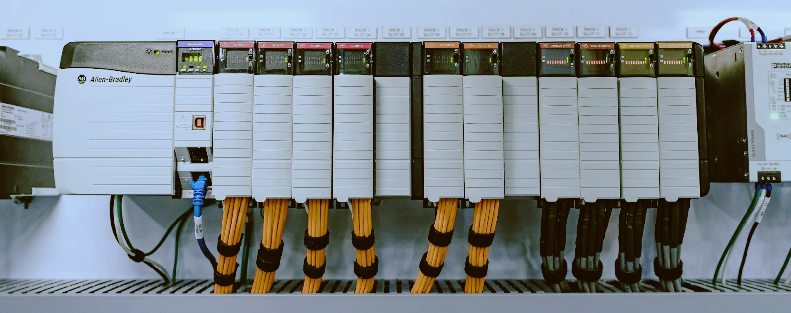
      The phone rang at 11 PM on a Tuesday. Ammonia refrigeration skid at a cold storage facility — the whole system dropped into fail-safe, product temperature climbing. The PLC-5 had a solid red PROC LED and no amount of power cycling brought it back. I swapped in a spare 1785-L80B, reloaded the program from a floppy disk, and had the refrigeration back online before the first pallet of frozen meat started to soften. That CPU ran continuously for fourteen years. It chose that night to die. The PLC-5 family was discontinued years ago. Last-order dates passed. But the installed base is enormous, and these systems do not fail on a schedule that suits your budget cycle.   Why Plants Still Run PLC-5 Systems   Replacing a working control system costs six figures and requires a plant shutdown. A PLC-5 running a batch reactor that has been making the same product since 1997 — the program is debugged, the operators know it, and the production manager has no appetite for a migration project that risks weeks of commissioning delays. The 1771 I/O rack and 1785 processors were built when Rockwell over-engineered everything. Gold-plated backplane connectors. Heavy-gauge steel chassis. A 1771-PS7 from 1992 will still regulate within spec if the capacitors have not dried out. I have seen PLC-5 systems running steel mill table drives, chemical batch sequencing, pipeline valve control, and half the automotive transfer lines built in the 1990s. The capital request for a migration sits in a drawer, waiting for a catastrophic failure or a budget year that never comes.   Common Failure Modes   After twenty-plus years in the field, here is what actually fails — not what the manual says can theoretically fail.   Power Supply Failures (1771-PS7)   The 1771-PS7 provides 5V and 24V DC to the backplane. The electrolytic capacitors inside have a finite life — roughly seven to ten years in a ventilated panel. In a sealed cabinet running at 50°C ambient, those caps drift out of spec in five years. Symptoms of a failing PS7: · Intermittent rack faults clearing on power cycle · Flashing or dim PWR LED · Unexplained I/O communication errors on specific slots · 5V rail measuring below 4.75V on a multimeter When the PS7 fails completely, the entire rack goes dark. I carry a spare 1771-PS7 in my truck. The PS7 has a distinct failure signature depending on line voltage. On 120V/60Hz (North America), rectifier diodes tend to fail before the caps. On 230V/50Hz (Europe, Middle East), input filter capacitors fail first — the higher RMS voltage stresses the dielectric harder. Stock with CE and UL certification requirements in mind.   Battery-Backed RAM Loss   The 1785 processors use a 3.6V lithium battery (1770-XY) to maintain the user program in SRAM when main power is off. Below approximately 3.0V, the CPU sets a BAT LED warning. Below 2.5V, you have an empty CPU. The critical detail: the battery drains faster when the CPU is powered on than when it is off. A 1785-L80B running continuously drains its battery in twelve to eighteen months — about half the life of the same battery in a powered-off spare. Replace the backup battery every twelve months, on a schedule. Write the replacement date inside the cabinet door with a paint marker. I have seen plants lose programs because the maintenance manager assumed the battery lasts five years. It does not in a warm panel running 24/7. Specific processor models to watch: · 1785-L80B — Full-featured processor with 256K memory. Highest battery drain due to larger SRAM array. Check BAT LED quarterly. · 1785-L40B — Mid-range processor, 128K memory. Slightly longer battery life than the L80B. When the program is lost, you need three things: the backup file (.RSP from RSLogix 5), the correct processor firmware, and a working connection to download.   1771 I/O Module Faults   The 1771-IBD uses optical isolators that degrade over time. After fifteen to twenty years, the current transfer ratio drifts. The input stops reliably detecting the OFF state — the CPU sees a logic 1 when the field device is de-energized. Replace the module when you see phantom ON states. 1771-OB (24V DC Sourcing Output) — The Darlington transistor arrays fail shorted or open. A shorted output keeps the load energized when the logic says OFF. The 1771-OB has no output fuse. Keep spares. 1771-IXE (Thermocouple/Millivolt Input) — Uses a custom hybrid ASIC that is no longer manufactured. When the ASIC fails, the module outputs random values or locks at a fixed reading. These are getting expensive on the secondary market because new-old-stock is exhausted.   RSLogix 5 Software Compatibility   RSLogix 5 is the only way to program and troubleshoot the PLC-5 family. Rockwell stopped selling new licenses years ago. Version 8.20 is the last release — a 32-bit application running on Windows 7 and Windows 10 in compatibility mode. Windows 11 is unreliable. Common RSLogix 5 issues in 2026: · DH+ communication via 1784-PCMK — The PCMCIA card is obsolete. Driver support ended with Windows 7. USB-to-DH+ converters (1784-U2DHP) cost $500-$1,200 and are themselves discontinued. · Serial DF1 upload — Requires a real RS-232 port. FTDI chipset-based USB adapters are the most reliable. Prolific-based adapters cause random corruption. · Ethernet upload (1785-L80C/L80E) — The most reliable method if your processor has Ethernet. Set a static IP, connect directly with a crossover cable, and use the Who Active feature. · Program file corruption — RSLogix 5 uses a serialization scheme. If an uploaded .RSP file will not download back to the CPU, create a new file and upload data tables first, then the program separately. Keep a dedicated laptop running Windows 7 or Windows 10 32-bit with RSLogix 5 installed. Do not let IT update it. Do not connect it to the internet.   Replacement Options: ControlLogix vs CompactLogix   You will eventually have to migrate. Here is the realistic breakdown.   ControlLogix Migration   The native replacement for PLC-5 is ControlLogix — the 1756-L8x series. Rockwell provides a migration toolkit that converts most ladder logic automatically. Simple discrete logic converts cleanly. PID loops, MSG instructions, and block transfers (BTR/BTW) require manual rework. Cost: a single ControlLogix chassis, processor, power supply, and communication module runs $5,000-$8,000 list. A full cabinet migration for a medium system (128 I/O points) runs $30,000-$60,000 in parts and engineering.   CompactLogix Migration   CompactLogix (5069-L3x or 5069-L4x series) is the lower-cost alternative at $2,000-$4,000 per processor. The 5069 I/O modules cost about 30% less than 1756 modules. Trade-offs: · CompactLogix supports fewer I/O points per chassis · No DH+ or Remote I/O built in — requires explicit communication modules · The 5069 backplane does not support 1771 adapter modules — all new I/O required For small to medium PLC-5 systems (under 128 I/O points), CompactLogix is the sensible choice. For large systems with significant analog I/O or existing ControlNet/RIO networks, the ControlLogix path saves integration headaches. The Reality of Migrations   Some vendors pitch a PAC migration as a drop-in replacement. It is not. The backplane, I/O, power supply, and programming environment all change. The only thing you keep is the field wiring. Budget for a complete system replacement.   Where to Find Spare Parts Today   New-old-stock PLC-5 and 1771 components are disappearing from traditional distribution. Rockwell does not manufacture them anymore. The remaining supply lives in the surplus and independent distributor network. Your best sourcing strategy: buy from an industrial automation spare parts specialist with tested inventory. At tztechio.com, the Allen-Bradley category carries curated PLC-5 processors, 1771 I/O modules, power supplies, and chassis — including 1785-L80B and 1785-L40B processors, 1771-IBD and 1771-OB I/O, and hard-to-find modules like the 1771-IXE thermocouple input. Broader PLC parts for other legacy platforms are also available.   What to Stockpile Now   If you maintain PLC-5 systems, supply tightens every quarter. Priority order: 1. 1771-PS7 power supply — Most common failure point. Stock two per active chassis. 2. 1785-L80B or L40B processor — One spare CPU per two systems. Buy tested units with verified battery backup circuitry. 3. 1770-XY batteries — Buy a case of twelve. Change every twelve months across all systems. 4. 1771-IBD and 1771-OB — Two of each per system. Highest failure rate among I/O modules. 5. 1771-IXE or other analog input modules — One spare per module type. Hardest to find. 6. 1771 chassis — One spare backplane per system size. A cracked chassis means full rewiring. 7. RSLogix 5 installation media and license — If you do not have it, find a licensed copy now. When your programming laptop dies, you will not be able to set up a new one.   What This Means for Your Plant   The PLC-5 is not coming back. Rockwell will not re-release it. Every day makes spare parts harder to find and more expensive. The plant manager who says "we will migrate next year" has been saying that for five years. The refrigeration skid CPU I replaced at 11 PM that Tuesday night was the same one the plant planned to migrate in 2019. Keep spares. Change batteries. Maintain your RSLogix 5 laptop. And when the budget appears for a migration, do it before the PLC-5 fails — not after. A controlled migration beats an emergency replacement every time. ------------------------------------------------------------------------------------------------------------------- 🏢 About TZ Tech   TZ Tech is a leading supplier of industrial automation, electrical, instrumentation, and telecommunications components. We specialize in sourcing ready-to-ship distributor stock, allowing us to offer highly competitive pricing and short lead times. Thanks to our extensive inventory, we can even source rare and discontinued parts that are hard to find elsewhere.   🛡️ Our Quality Commitment   We understand that quality is your top priority. Every component undergoes a strict screening and inspection process so you can buy with absolute confidence. For legacy or discontinued parts, we believe in complete transparency and will always provide an honest, accurate report on the product's condition. Plus, all brand-new parts come backed by a full 1-year warranty.   ✉️ Get in Touch     Have a project or a part you need? Send us your inquiry today! Our team is dedicated to providing a fast response within 6 hours (excluding weekends).

  • Fuji Electric MICREX PLC: Migration Options for End-of-Life Systems
    Fuji Electric MICREX PLC: Migration Options for End-of-Life Systems Jul 14, 2026
      Fuji Electric has been a dominant force in industrial automation across Japan and Southeast Asia for decades, with its MICREX PLC family installed in thousands of factories handling food processing, material handling, and water treatment. But the landscape has shifted. Fuji Electric has consolidated its programmable controller lineup around the SPH5000 and SPH3000M platforms, and the older generations — the MICREX-SX SPH200/300/500 series, the MICREX-NX family, and early SPH1000 systems — have all reached or are approaching end-of-life. If you are maintaining a line built around one of these legacy controllers, you face a familiar industrial dilemma: keep sourcing replacement parts on the used market, or commit to a migration project. Neither path is risk-free. The right answer depends on your specific hardware revision, I/O count, tolerance for downtime, and long-term production plan. Here are the five questions that come up most often when engineers realize their Fuji MICREX system is no longer fully supported. The answers are model-specific and grounded in what's actually available in 2026.   1. Which Fuji Electric MICREX Models Are Obsolete?   Fuji Electric has published formal end-of-life notices for several MICREX families. Here is the current status as of mid-2026: MICREX-SX SPH200 Series (Discontinued — No Factory Support) The SPH200 was Fuji's entry-level modular PLC in the MICREX-SX lineup. CPU models like the NP1FH-200 and NP1PH-200 were discontinued more than a decade ago. Fuji stopped accepting repair orders for these CPUs in 2019. If you have an SPH200 on your line, you are already running on whatever spare stock exists in the channel. MICREX-SX SPH300 Series (Discontinued — Support Ended) The SPH300 (CPU models NP1FH-300, NP1PH-300, NP1PS-300) was the mid-range workhorse of the MICREX-SX family. Formally discontinued in 2020, the five-year post-discontinuation support window has now closed in all regions. In Japan and parts of SE Asia, depot repair for emergency cases may still be available through authorized distributors with old stock of spare CPU boards, but wait times have stretched from weeks to months. MICREX-NX Series (Obsolete — No Support) The MICREX-NX family predates the MICREX-SX line and uses a completely different backplane and I/O form factor. Models like the NX-32, NX-64, and NX-128 CPU units have been out of production since the early 2000s. Spare parts are only available through third-party brokers or surplus dealers. MICREX-SX SPH500 Series (End-of-Life Active) The SPH500 (CPU models NP1PH-500, NP1PS-500) shares the same backplane form factor as the SPH1000 and SPH3000M, but Fuji is phasing it out in favor of the SPH5000M. Factory support is expected to end completely by 2028. Fuji still manufactures replacement CPU modules for warranty contracts, but new-unit pricing has increased 30-40% since 2023 as production volumes dropped. MICREX-SX SPH1000 Series (Support Phasedown) The SPH1000 (CPU models NP1PS-1000, NP1PH-1000) bridges the gap between old MICREX-SX and the current SPH5000 architecture. Fuji still sells these CPUs, but lead times for factory orders have stretched to 12-16 weeks. Fuji recommends the SPH5000M as the direct replacement for new projects. Key takeaway: If your CPU is an SPH200 or SPH300, you are past the point of factory support. SPH500 and SPH1000 users have a narrowing migration window — roughly 12 to 24 months depending on your region. --- 2. Can I Replace a MICREX-SX with an SPH Directly?   This is the single most common question from engineers managing Fuji lines. Short answer: it depends on the CPU generation. Physical Compatibility — I/O Modules The good news: Fuji Electric maintained the same backplane form factor across the SPH200, SPH300, SPH500, SPH1000, SPH3000M, and SPH5000M families. Your existing I/O modules — digital input modules like NP1X32-DC24, analog modules like NP1A04-AD, and specialty modules like NP1CN1 (T-LINK), NP1CN2 (FL-net), and NP1CN3 (PROFIBUS) — can be taken out of the old rack and plugged directly into a new SPH5000M rack. The I/O bus protocol is electrically compatible across these generations, making a CPU-only swap physically possible. CPU and Firmware — Not a Direct Swap The catch is the CPU module and programming environment. An SPH5000M CPU (model NP1PS-5000M or NP1PH-5000M) will not run SX-Programmer project files compiled for an SPH200 or SPH300 without significant rework. The instruction set expanded between generations. Memory maps for T-LINK and FL-net communication areas changed. Interrupt handling and task scheduling that worked on the SPH300 may behave differently on the SPH5000M. What this means in practice: you can keep your field wiring, I/O rack, power supplies, and base modules. You will need to rewrite the application logic in Standard SX-Programmer or the newer NP (Nano Programming) environment and revalidate it. Practical Drop-In Path The most straightforward migration path is SPH1000 → SPH5000M. If you have an SPH1000 running Standard SX-Programmer projects compiled under V6.x or later, the conversion involves recompiling the project, checking communication configuration, and swapping the CPU module. For SPH200/300 users on older SX-Programmer V3.x/V4.x projects, expect a full program rewrite. --- 3. What Programming Software Works with Legacy vs. New Fuji PLCs?   Software compatibility is often the make-or-break factor in any MICREX migration. Using the wrong software version can corrupt project files or fail to communicate with the CPU entirely. SX-Programmer (Legacy — SPH200/300/500) The original SX-Programmer, typically V3.x through V5.x, is the only software that can compile and download logic to SPH200 and SPH300 CPUs. It runs on Windows XP through Windows 7 (32-bit). It does not install correctly on Windows 10 or 11 without a virtual machine. Communication uses the SX bus protocol over RS-232C or USB-to-serial adapters with the NP1W-CN1 cable. If you need to maintain an SPH200 or SPH300 line, keep a dedicated Windows 7 PC with SX-Programmer V5.2 or later. Standard SX-Programmer (Transition — SPH1000/SPH3000M) Standard SX-Programmer V6.x and V7.x supports the SPH1000, SPH3000M, and early SPH5000M firmware revisions. It runs on Windows 7 and Windows 10 (64-bit) and uses a different project file format (.sxp vs. the older .sxc). Projects created in V3.x/V4.x must be manually re-created — there is no automatic conversion utility. This version also introduced device configuration files for EtherNet/IP and PROFINET modules. If your legacy system used T-LINK or FL-net, expect to reconfigure communication parameters from scratch. NP (Nano Programming) Software (Current — SPH5000M) Fuji Electric's current programming environment, NP software, supports the SPH5000M and SPH3000M with the latest firmware. It runs on Windows 10 and Windows 11 (64-bit) and provides structured text (ST), ladder diagram (LD), and function block diagram (FBD) editors. NP software does not support SPH200, SPH300, or SPH500 CPUs at all — connecting to these older CPUs will fail at the communication handshake. NP projects are not backward-compatible with Standard SX-Programmer. Legacy CPU | Required Software | Migration Path SPH200/300 | SX-Programmer V3-V5 | Full rewrite in Standard SX-Programmer or NP SPH500 | SX-Programmer V5+ | Standard SX-Programmer V6/V7 → export to NP SPH1000 | Standard SX-Programmer V6/V7 | Recompile in NP + revalidate SPH5000M | NP software (current) | Current platform — no migration needed --- 4. What's the Cost of Migrating vs. Sourcing Used Parts?   Cost is where the numbers get real — and rarely as clean as the vendor brochures suggest. Sourcing Used Parts — The Short-Term Path A used SPH300 CPU (NP1PH-300) on the surplus market ranges from $150 to $400 depending on condition and revision. A used SPH500 CPU runs $350 to $700. I/O modules are cheaper: $30 to $80 for digital inputs, $80 to $200 for analog modules. The math looks attractive for a single CPU swap. The risk is buying a component with unknown runtime hours, stored in uncontrolled conditions, with no warranty beyond "tested on power-up." We have seen buyers receive CPUs with corroded battery contacts, expired firmware revisions, or modules that passed a bench test but failed after three weeks of production vibration. If your line runs 24/7 and downtime costs $5,000+ per hour, one unexpected failure of a used CPU wipes out any apparent savings. Migration — The Long-Term Path A full migration from an SPH300 to an SPH5000M typically costs $8,000 to $18,000 per cabinet in hardware (CPU, memory card, power supply, communication modules). Labor for programming, panel rework, and commissioning adds $5,000 to $12,000 per cabinet depending on program complexity. For a 256-I/O-point food processing skid running an SPH500, budget $15,000 to $20,000 for a full migration. For a 512-point water treatment line with multiple SPH300 CPUs on T-LINK, expect $25,000 to $40,000. The Breakeven Calculation The breakeven point comes when you have replaced a critical CPU more than once. Buy a used SPH300 for $350, it runs 14 months, fails, and you buy another for $400 plus $150 emergency shipping — you are at $900 with no guarantee the third unit lasts longer. At that point, the migration cost looks like an investment in reliability. For plants running MICREX-NX systems, used parts are the only option since Fuji no longer manufactures compatible components. Migration requires replacing the entire backplane and I/O infrastructure, pushing costs to $30,000+ per cabinet. Regional Factors In Japan and SE Asia, used Fuji MICREX parts are 15-25% cheaper than in North America or Europe, reflecting the larger installed base. In the Middle East — particularly UAE, Saudi Arabia, and Qatar food processing plants — Fuji spare parts command a 30-40% premium because most must be imported from Japan or Singapore with 4-6 week lead times. --- 5. Where Can I Find Spare Parts for Legacy MICREX Systems?   When factory support runs out, the secondary market becomes essential. Here is where engineers actually source Fuji MICREX spare parts in 2026. Specialized Automation Parts Suppliers For a broad inventory of Fuji MICREX CPUs, I/O modules, power supplies, and communication modules, your best source is a dedicated industrial automation parts supplier like TZ Techio, which stocks new-old-stock and tested used components across the SPH200, SPH300, SPH500, SPH1000, and SPH3000M families. These suppliers typically test each module before listing and offer a 30-day warranty. Japanese Surplus Brokers Companies like Nippon Avionics and Marubun, along with regional surplus houses in Osaka and Nagoya, are primary clearinghouses for decommissioned Fuji equipment. Pricing is competitive if you buy direct, but requires Japanese-language capability and a freight forwarder. Expect minimum order quantities of 3-5 units for CPUs. Auction Platforms Yahoo! Japan Auctions and Mercari Japan are the deepest markets for used Fuji MICREX parts, but they require a proxy buying service (Buyee, FromJapan). We estimate 60-70% of all used Fuji PLC parts change hands through Japanese domestic channels before appearing in international listings. By the time a module hits eBay or Alibaba, it has typically been marked up 50-100%. What to Stockpile If you plan to keep a legacy MICREX system running another 3-5 years, prioritize: 1. CPU module — the most failure-prone and hardest to source over time 2. Battery backup module (CR123A-based) — ages on the shelf and fails silently 3. Communication modules (T-LINK NP1CN1, FL-net NP1CN2) — no substitutes available 4. Power supply module — electrolytic capacitors age regardless of runtime --- Decision Guide: Migrate or Source Spare Parts?   Use this table to evaluate your specific situation. No single answer fits every plant. Factor | Migrate to SPH5000M | Source Used Parts Current CPU | SPH500 or newer | SPH200/300 or MICREX-NX I/O count | 128+ points | Under 128 points Line criticality | 24/7 uptime required | Non-critical or backup line Support window | Need warranty, factory support | Can tolerate unplanned downtime Budget horizon | 5+ year ROI on reliability | 12-18 month horizon Geography | North America, Europe, Middle East | Japan, SE Asia (good parts availability) Software status | Have Standard SX-Programmer V6+ | Running legacy SX-Programmer V3-V5 Spare CPU cost | N/A (new) | Under $300 each Risk tolerance | Low — cannot absorb random failure | High — can swap and recover For plants running SPH200 or SPH300 CPUs with fewer than 128 I/O points on non-critical lines, sourcing used parts is defensible for the next 18-24 months. Stockpile two spare CPUs, a handful of I/O modules, and backup batteries. Monitor the surplus market quarterly — SPH300 CPU prices have been climbing 8-12% per year as supply contracts. For every other scenario — particularly SPH500 or SPH1000 users in North America, the Middle East, or Europe — the migration math favors the SPH5000M. The window for an orderly, planned migration is narrowing. If you need to locate specific Fuji MICREX spare parts or compare pricing on new-old-stock modules, browse the PLC category at TZ Techio or explore the broader industrial automation inventory. A reliable supply chain for legacy hardware — or a clear migration path to current platforms — is the difference between a scheduled upgrade and an emergency shutdown. ----------------------------------------------------------------------------------------------------------------- 🏢 About TZ Tech   TZ Tech is a leading supplier of industrial automation, electrical, instrumentation, and telecommunications components. We specialize in sourcing ready-to-ship distributor stock, allowing us to offer highly competitive pricing and short lead times. Thanks to our extensive inventory, we can even source rare and discontinued parts that are hard to find elsewhere.   🛡️ Our Quality Commitment   We understand that quality is your top priority. Every component undergoes a strict screening and inspection process so you can buy with absolute confidence. For legacy or discontinued parts, we believe in complete transparency and will always provide an honest, accurate report on the product's condition. Plus, all brand-new parts come backed by a full 1-year warranty.   ✉️ Get in Touch     Have a project or a part you need? Send us your inquiry today! Our team is dedicated to providing a fast response within 6 hours (excluding weekends).
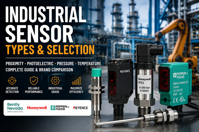
  • WAGO 750 Series PLC Programming: A Step-by-Step Guide for First-Time Users
    WAGO 750 Series PLC Programming: A Step-by-Step Guide for First-Time Users Jul 13, 2026
    What You Need   Hardware · WAGO 750-8212 PFC200 controller (dual-Ethernet, 1 GHz Cortex-A8, 512 MB RAM) · WAGO 750-341 4-channel digital input module (24 VDC sink/source) · WAGO 750-430 4-channel digital output module (24 VDC, 0.5 A per channel) · WAGO 750-600 end module (mandatory bus termination — system will not power without it) · 24 VDC power supply (Class 2 supply for UL-compliant installations) · Ethernet cable, straight-through Cat5e · Windows PC (CODESYS does not run on Linux or macOS) Software · CODESYS 3.5 SP19 or later (download from the CODESYS Store or WAGO website) · WAGOAddOn for CODESYS (device description files for all 750-series controllers) · A free CODESYS license works for initial programming. Production deployments need a runtime license ($150–$350 USD depending on feature tier). Power: The 750-8212 accepts 24 VDC (20.4–28.8 VDC). For 120 VAC/60 Hz sites, use a WAGO 787-1622 DIN-rail supply. For 230 VAC/50 Hz installations, the WAGO 787-1661 fits. Both are CE and UL 508 listed.   Step 1: Install CODESYS 3.5   1. Download CODESYS 3.5 SP19 from the CODESYS Store or the WAGO portal. 2. Run the installer as Administrator. Accept all defaults. 3. Download and install the WAGOAddOn for CODESYS package. This loads device descriptions for the 750-8212, 750-8202, 750-810, and all legacy controllers. 4. Launch CODESYS. Go to Tools → Device Repository and confirm WAGO PFC200 750-8212 appears in the list. If not, restart CODESYS and re-run the AddOn installer. Common issue: Device description files are service-pack-specific. Installing AddOn for SP16 on CODESYS SP19 leaves you with zero devices listed. Match the AddOn version to your CODESYS service pack exactly. --- Step 2: Create a New Project   5. Click File → New Project. 6. Select Standard Project. 7. Name the project `WAGO_Motor_Start_Stop`. Pick a save folder you will remember. 8. In the Device dropdown, select WAGO PFC200 (750-8212) . In PLC_PRG in, select Ladder Logic Diagram (LD) . 9. Click OK. The workspace opens with the device tree on the left showing the controller and one POU named PLC_PRG. --- Step 3: Configure the 750 Controller   Right-click WAGO PFC200 (750-8212) in the device tree and select Add Device. · Add a WAGO 750-341 digital input module (bus address 1). · Add a WAGO 750-430 digital output module (bus address 2). · Add a WAGO 750-600 end module at the bus end (models the physical bus correctly in software). ETHERNET vs fieldbus addressing: The 750-8212 uses ETHERNET for programming by default. If you integrate into a PROFIBUS network, you need a separate coupler (e.g., 750-375) and configure its address under the Fieldbus Configuration tab — not the Ethernet settings. First-time users frequently confuse the programming IP with the fieldbus station address. They live in different menus. IP address: Double-click the controller node, go to the Ethernet tab, and assign a static IP — e.g., 192.168.1.10 with mask 255.255.255.0. Write this on the controller enclosure. You need it for every download. Firmware check: Open the Information tab on the controller node. CODESYS 3.5 SP19 requires firmware v21 or later on the 750-8212. Controllers shipping with v18 or v19 need an update using the WAGO Firmware Update Tool (separate download) before your first program download. A firmware mismatch produces a silent failure — the download completes, the controller reboots, and the old program stays in memory. --- Step 4: Write a Simple Program — Motor Start/Stop with Interlocks   Write a standard three-wire motor control circuit — the PLC equivalent of pushing a button to make something happen. Open PLC_PRG. Declare these variables in the top pane: ` PROGRAM PLC_PRG VAR Start_PB    : BOOL;   (* Start pushbutton — NO, 24 VDC *) Stop_PB     : BOOL;   (* Stop pushbutton — NC, 24 VDC *) Motor_Run   : BOOL;   (* Motor contactor output *) Overload    : BOOL;   (* Thermal overload relay — NC *) END_VAR ` Map variables to I/O: Double-click WAGO 750-341 in the device tree. Map Start_PB to %IX1.0 (channel 0), Stop_PB to %IX1.1, Overload to %IX1.2. Then double-click WAGO 750-430 and map Motor_Run to %QX2.0. Alternatively, use the PLC_PRG I/O mapping table for a dropdown interface. Ladder logic in CODESYS: Drag contacts and coils from the Toolbox onto the rung. Build two rungs. Rung 1 (seal-in): ` Start_PB              Motor_Run ----| |----------------------( )---- Motor_Run ----| |----(parallel branch to Start_PB) ` Rung 2 (stop and overload in series): ` Stop_PB     Overload    Motor_Run ----|/|----------|/|-----------( )---- ` Right-click contacts to toggle between normally-open (| |) and normally-closed (|/|). Add a parallel branch by right-clicking below the Start_PB contact and selecting Add Branch. The logic reads: pressing Start_PB energizes Motor_Run. Motor_Run seals itself in through its own NO contact. Pressing Stop_PB or tripping Overload breaks the circuit and drops Motor_Run. This three-wire pattern translates directly to physical motor starter wiring — you can test the PLC against a real contactor without modifying the code. --- Step 5: Download and Test   10. Connect the 750-8212 to your PC with the Ethernet cable. 11. Power the controller. The RUN and I/O LEDs flash during boot. Wait for a steady RUN LED (about 30 seconds). 12. In CODESYS, click Online → Login (or press F11). 13. At the Select Network Path prompt, click Scan Network. The controller appears as `WAGO PFC200 (750-8212) @ 192.168.1.10`. Select it and click OK. 14. Click Yes to download the application. 15. The controller enters RUN mode automatically after the download completes. 16. Switch to Online → Toggle Watch View (F9). Ladder rungs highlight green when contacts and coils are active. Test sequence: · Momentarily short pin 1 (Start_PB) to 24 VDC on the 750-341. `Start_PB` turns green in the watch view and `Motor_Run` energizes. · Momentarily short pin 2 (Stop_PB) to 24 VDC. `Stop_PB` turns green and `Motor_Run` drops out. · Repeat with pin 3 (Overload) to confirm the interlock holds. If Motor_Run does not energize, check wiring polarity on the 750-430 — outputs are sink/source configurable via the common terminal. --- Common Pitfalls with WAGO CODESYS Setup   17. Firmware mismatch. You download the program, CODESYS says "Application downloaded successfully," the controller reboots, and nothing runs. The firmware on the 750-8212 is older than the project requires. Check the Information tab against your CODESYS SP compatibility matrix. Update firmware before the first download. 18. End module missing. Without the 750-600, the internal bus never initializes. The I/O LED flashes red. Fit the 750-600 at the right end of the DIN-rail assembly. 19. Subnet mismatch. CODESYS scans the local subnet only. PC on 192.168.0.x, controller on 192.168.1.10 — the scan finds nothing. Match subnets or add a secondary IP on your PC's adapter. 20. Wrong I/O mapping. Verify Start_PB maps to %IX1.0 (750-341, channel 0) and not %IX1.1. A swapped bit reads the wrong pushbutton. Use the I/O Mapping tab on each bus coupler node. 21. Expired trial license. CODESYS runtime on the 750-8212 runs in trial mode for 2 hours. After that, the controller stops executing user code. Purchase a runtime license ($250–$350 USD for the PFC200) and activate it via the CODESYS License Manager before commissioning. --- Checklist for First-Time Users   · CODESYS 3.5 installed with matching WAGO AddOn version · Controller firmware updated to v21 or later · Static IP assigned and written down · 750-600 end module fitted on the DIN rail · I/O modules added in the device tree in correct bus order · Variables declared and mapped to the correct bus addresses · Ladder logic compiles without errors (green checkmark in Messages pane) · PC and controller on the same subnet · Login successful — green triangle in the status bar · Pushbutton test passes: Start energizes, Stop drops, Overload holds · Runtime license activated or trial timer noted Next steps: Add analog modules (750-455, 750-456) for sensor feedback. Configure the second Ethernet port on the 750-8212 for plant network isolation. Set up a WebVisu dashboard for remote monitoring. Implement Modbus TCP master/slave to talk to a VFD. For all WAGO 750 series parts — controllers, I/O modules, power supplies, and accessories — check current stock and pricing at tztechio.com/plc. We carry new and certified pre-owned WAGO automation hardware with CE and UL marks, ready to ship. -------------------------------------------------------------------------------------------------------------------- 🏢 About TZ Tech   TZ Tech is a leading supplier of industrial automation, electrical, instrumentation, and telecommunications components. We specialize in sourcing ready-to-ship distributor stock, allowing us to offer highly competitive pricing and short lead times. Thanks to our extensive inventory, we can even source rare and discontinued parts that are hard to find elsewhere.   🛡️ Our Quality Commitment   We understand that quality is your top priority. Every component undergoes a strict screening and inspection process so you can buy with absolute confidence. For legacy or discontinued parts, we believe in complete transparency and will always provide an honest, accurate report on the product's condition. Plus, all brand-new parts come backed by a full 1-year warranty.   ✉️ Get in Touch     Have a project or a part you need? Send us your inquiry today! Our team is dedicated to providing a fast response within 6 hours (excluding weekends).
  • What is a PLC? A Beginner's Complete Guide to Programmable Logic Controllers
    What is a PLC? A Beginner's Complete Guide to Programmable Logic Controllers May 08, 2026
      Introduction A PLC (Programmable Logic Controller) is a ruggedized, industrial-grade digital computer designed to automate electromechanical processes in manufacturing plants, machines, and infrastructure. Unlike regular commercial computers, PLCs are built to withstand harsh industrial conditions: temperature extremes, humidity, dust, electrical noise, and vibration. The PLC's role is straightforward: it reads inputs, makes decisions based on programmed logic, and controls outputs. Think of it as the "brain" of a machine or process—when a pushbutton is pressed (input), the PLC decides what should happen (logic) and activates a motor, valve, or indicator (output). The History: Why PLCs Were Invented Before PLCs, industrial automation relied on relay panels—large cabinets filled with hundreds or thousands of electromechanical relays, timers, and contactors. Problems included: physically rewiring for any change (taking days or weeks), mechanical wear causing downtime, difficult troubleshooting, enormous space requirements, and no data collection capability. In 1968, Bedford Associates (later Modicon) developed the first PLC—the Modicon 084—for General Motors' Hydra-Matic transmission plant. The goal was simple: replace relay panels with a programmable electronic system that could be reconfigured quickly when production changed. Within a decade, PLCs had largely replaced relay panels worldwide. PLC Hardware: Core Components 1. CPU (Central Processing Unit): The "brain" of the PLC—a microprocessor that runs the control program, performs arithmetic and logic operations, and manages communication. Key specs include memory size, scan time (ms), I/O capacity, and communication ports (Ethernet, USB, RS-232/RS-485). 2. Power Supply: Converts incoming AC mains power (110V/220V AC) to the DC voltages required by CPU and I/O modules (typically 24V DC). Critical considerations: power rating, redundancy for critical apps, and input voltage range. 3. Input Modules: Connect sensors and switches to the PLC CPU, converting real-world signals into digital data. Digital inputs (24V DC) accept pushbuttons, limit switches, proximity sensors, and pressure switches—representing only ON (1) or OFF (0). Analog inputs handle temperature sensors (RTD, thermocouple), pressure transducers, flow meters, and level sensors with signals like 4-20mA or 0-10V. 4. Output Modules: Receive commands from the CPU and control actuators. Digital outputs (24V DC, 120V AC, or relay) control solenoid valves, contactors, motor starters, indicator lights, and alarms. Analog outputs drive variable frequency drives (VFDs), proportional valves, and servo drives with standard signals like 4-20mA or 0-10V. 5. Rack/Backplane: The physical infrastructure holding all PLC modules together and providing the communication bus between them. 6. Communication Interfaces: PLCs communicate with HMIs, other PLCs, drives, and plant networks through protocols including EtherNet/IP, PROFINET, Modbus TCP/IP, PROFIBUS, DeviceNet, ControlNet, OPC UA, and serial connections (RS-232/RS-485). How Does a PLC Work? The Scan Cycle The CPU executes its program in a continuous, repetitive loop called the scan cycle. Each complete cycle consists of four steps: Step 1 – Read Inputs: The CPU reads all input module states and stores them in the input image table (typically 1-10ms). Step 2 – Execute Program: The CPU executes the user program one instruction at a time, reading from and writing to the input/output image tables in memory. Step 3 – Write Outputs: After program execution, the CPU updates all output modules simultaneously with values from the output image table. Step 4 – Housekeeping: The CPU performs internal tasks including HMI/PLC communication, time-based functions, and diagnostics. Typical scan time is 5-20ms for a medium-sized program; high-speed applications may require 0.5-1ms. PLC Programming Languages: The Five IEC 61131-3 Standards 1. Ladder Diagram (LD) – The most popular language, especially in North America. Designed to look like electrical relay schematics, making it intuitive for electricians. Best for discrete logic and sequential control. 2. Function Block Diagram (FBD) – Uses graphical blocks with input/output connections. Each block performs a specific function—PID loops, arithmetic, logic gates, timers. Best for process control and PID loops. 3. Structured Text (ST) – High-level text-based language similar to Pascal or BASIC. Most powerful for complex data processing, batch processing, and advanced state machines. 4. Sequential Function Chart (SFC) – Graphical language for defining sequential processes—operations that happen in steps with actions and controlled transitions. Best for batch processes and packaging machines. 5. Instruction List (IL) – Low-level text-based language similar to assembly language. Compact and efficient but less readable. Best for simple, compact routines and legacy systems. PLC vs. DCS vs. Industrial PC PLC: Designed for discrete manufacturing (individual machines, assembly lines). Fast scan times, ruggedized hardware. Scale: hundreds to thousands of I/O points. DCS (Distributed Control System): Designed for continuous process industries (oil & gas, chemical, power generation). Highly redundant, tightly integrated with process variables. Scale: thousands to hundreds of thousands of I/O points. Industrial PC (IPC): Designed for high-speed data processing, vision systems, and complex algorithms. PC-based, runs Windows or Linux with high computational power. The boundaries between PLC, DCS, and IPC have blurred significantly in recent years. How to Choose the Right PLC Step 1: Define the application—single machine or plant-wide system, high-speed motion control needs, safety-critical requirements, current and future I/O counts. Step 2: Evaluate the brand ecosystem—Allen Bradley dominates in the Americas, Siemens in Europe/Asia, Mitsubishi in Japan and cost-sensitive markets, ABB for process automation. Step 3: Consider software costs—hardware is often only 30-50% of total cost of ownership; software licensing can be equally expensive (Allen Bradley Studio 5000: $5,000-$15,000+). Step 4: Match I/O requirements—calculate digital inputs, digital outputs, and analog signals needed, adding 20% margin for future expansion. Step 5: Verify communication requirements—HMI connectivity, plant network integration (MES/ERP), drive/PLC communication, and remote access capability. Top PLC Brands at a Glance Allen Bradley (Rockwell Automation) Flagship products: ControlLogix, CompactLogix, MicroLogix, SLC 500 Programming software: Studio 5000 Logix Designer Communication: EtherNet/IP, ControlNet, DeviceNet, Modbus Website: www.rockwellautomation.com Siemens Flagship products: SIMATIC S7-1500, S7-1200, S7-300, S7-400 Programming software: TIA Portal Communication: PROFINET, PROFIBUS, Modbus TCP/IP, OPC UA Website: www.siemens.com Mitsubishi Electric Flagship products: MELSEC iQ-R, iQ-F, MELSEC-Q, MELSEC-F Programming software: GX Works3 Communication: CC-Link IE, Modbus TCP/IP, EtherNet/IP Website: www.mitsubishielectric.com ABB Flagship products: AC500, AC500-eco, AC700 Programming software: Automation Builder Communication: EtherNet/IP, PROFINET, Modbus TCP/IP, CANopen Website: new.abb.com/plc Honeywell Flagship products: ControlLogix (through Honeywell), Experion PKS Programming software: Experion Studio Communication: EtherNet/IP, Modbus, OPC UA Website: www.honeywellprocess.com Omron Flagship products: NX1P2, NJ501, CP1H, CP1L Programming software: Sysmac Studio, CX-Programmer Communication: EtherNet/IP, Modbus TCP/IP, USB Website: www.omron-ap.com This guide is for educational purposes. For specific application guidance, consult with a qualified automation engineer or contact TZ TECH's technical sales team.  
  • MASTERING THE CORE OF MODERN MANUFACTURING: A COMPREHENSIVE GUIDE TO PLC TECHNOLOGY
    MASTERING THE CORE OF MODERN MANUFACTURING: A COMPREHENSIVE GUIDE TO PLC TECHNOLOGY Apr 23, 2026
     The landscape of modern production has been irrevocably changed by a single device: the Programmable Logic Controller, or **PLC**. Whether you are exploring the basics of Industrial Automation or seeking advanced insights into IIoT (Industrial Internet of Things) integration, understanding the **PLC** is fundamental to navigating the future of the factory floor. This guide delves into the mechanics, programming, and troubleshooting of these robust industrial computers that keep the world’s assembly lines moving.   The Evolution: From Relays to Software-Defined Logic   Before the **PLC** was introduced in the late 1960s, industrial control relied on massive banks of mechanical relays. If a manufacturer wanted to change a production sequence, technicians had to physically rewire thousands of connections—a process that was time-consuming, expensive, and prone to human error.   The birth of the first **PLC**, the Modicon 084, revolutionized the industry by allowing logic to be programmed via software rather than physical wires. Today, global leaders like **Siemens**, **Allen-Bradley** (Rockwell Automation), and **Schneider Electric** have pushed this technology to the edge, creating controllers that are not just binary switches, but powerful data hubs capable of complex calculations and high-speed communication.   Decoding PLC Programming: The Languages of Automation   For many entering the field, **PLC programming** is the most daunting yet rewarding aspect of the technology. The international standard IEC 61131-3 defines five distinct languages, each suited for different tasks within Industrial Automation.   1. Ladder Logic (LD): The most iconic language, modeled after electrical relay diagrams. It is the go-to for technicians because it is highly visual and easy to monitor in real-time. 2. Structured Text (ST): A high-level language similar to Pascal or C. It is increasingly popular for complex mathematical algorithms and data handling, favored by a new generation of engineers who are comfortable with traditional IT coding. 3. Function Block Diagram (FBD): This graphical language allows programmers to "wire" blocks of pre-written code together. It is widely used in process industries by brands like **ABB** and **Honeywell**. 4. Sequential Function Chart (SFC): Ideal for step-by-step processes, such as a batch mixing sequence in a food plant. 5. Instruction List (IL): A low-level assembly style, now less common but still found in older legacy systems.   The IIoT Revolution: Connecting the Shop Floor to the Top Floor   The most significant trend in 2026 is the convergence of OT (Operational Technology) and IT (Information Technology). This is where the **IIoT** comes into play. Modern **PLC** systems are no longer isolated. Through protocols like OPC UA and MQTT, a **PLC** can now stream real-time performance data directly to cloud platforms like AWS or Azure.   Why does this matter? For a business owner, it means "Data-Driven Decision Making." If an **Omron** or **Keyence** controller on the line detects a slight increase in motor temperature or a millisecond delay in cycle time, that data is instantly analyzed by AI in the cloud to predict a failure before it happens. This transition from reactive maintenance to predictive maintenance is the hallmark of Industry 4.0.   Professional PLC Troubleshooting: A Systematic Approach   Even the most sophisticated systems encounter issues. Masterful **PLC troubleshooting** is what separates a senior engineer from a novice. When a machine stops, the **PLC** is your best diagnostic tool.   - Hardware Diagnostics: Always start with the physical layer. Check the power supply and look for "Fault" lights on the CPU. Brands like **Mitsubishi** and **Delta** have intuitive LED indicators that can pinpoint a failed I/O module in seconds. - Software Monitoring: By going "online" with the controller using software like TIA Portal or Studio 5000, you can see the logic execute in real-time. If a "rung" isn't turning green, you can trace the input back to a faulty limit switch or a broken wire. - Forcing I/O: This is a powerful but dangerous technique. You can manually "force" an output to turn on to test a valve or motor. However, professional **PLC troubleshooting** safety protocols dictate that you must ensure no personnel are near the moving parts before doing so.    
  • BEYOND THE FIREWALL: SECURING PLC NETWORKS IN THE AGE OF IIOT AND EDGE COMPUTING
    BEYOND THE FIREWALL: SECURING PLC NETWORKS IN THE AGE OF IIOT AND EDGE COMPUTING Apr 16, 2026
    BEYOND THE FIREWALL: SECURING PLC NETWORKS IN THE AGE OF IIOT AND EDGE COMPUTING Industrial automation is undergoing a radical transformation. What were once isolated "islands of automation" are now nodes on a global network. While the integration of the Programmable Logic Controller (PLC) with cloud-based analytics has unlocked unprecedented levels of efficiency, it has also opened the door to sophisticated cyber threats. For modern engineers, PLC programming is no longer just about logic and timing—it is about building resilient, secure architectures that can withstand the evolving landscape of industrial espionage and ransomware.   The Shift from Air-Gapped to Hyper-Connected Systems For decades, the primary defense for a PLC was the "air gap"—the physical isolation of the factory floor from the internet. However, the rise of Industrial Automation 4.0 has made the air gap a relic of the past. To leverage IIoT (Industrial Internet of Things) benefits, such as remote monitoring and predictive maintenance, controllers from brands like Siemens, Allen-Bradley, and Schneider Electric must communicate with Enterprise Resource Planning (ERP) systems and cloud dashboards. This connectivity creates "attack vectors." A vulnerability in a workstation or a misconfigured VPN can allow an attacker to reach the plant floor. Once inside, they can modify PLC programming, alter setpoints, or even disable safety interlocks, leading to catastrophic equipment failure or production downtime. Understanding Common PLC Vulnerabilities To implement effective PLC troubleshooting and security, one must understand where the weaknesses lie. Most legacy industrial protocols, such as Modbus TCP or early versions of EtherNet/IP, were designed for performance, not security. They often lack encryption and authentication, meaning that any device on the network can send commands to the PLC. Key vulnerabilities in modern systems include: · Insecure Communication Protocols: Data sent in "clear text" can be intercepted or spoofed. · Legacy Firmware: Many controllers in the field run firmware that is years out of date, containing known exploits. · Unprotected Engineering Ports: Ports used for PLC programming and diagnostics are often left open and unmonitored.  · Weak Credential Management: Default passwords or shared accounts across the maintenance team. · Defense-in-Depth: A Multi-Layered Security Strategy Securing a factory requires a "Defense-in-Depth" approach. This means relying on multiple layers of security so that if one fails, others are in place to stop the threat. 1. Network Segmentation and Micro-segmentation The first line of defense is separating the Industrial Control System (ICS) network from the standard office network. Using industrial firewalls and VLANs (Virtual Local Area Networks), you can ensure that only authorized traffic moves between the PLC and the outside world. Leading brands like Phoenix Contact and Moxa provide specialized hardware to manage this boundary. 2. Implementing Secure Protocols (OPC UA and Beyond) Transitioning from legacy protocols to secure alternatives is vital. OPC UA (Open Platform Communications United Architecture) has become the gold standard for secure Industrial Automation. It supports digital certificates and encryption, ensuring that the PLC only accepts commands from verified sources. 3. Hardening the PLC Hardware Modern controllers, such as the Siemens S7-1500 or the Allen-Bradley ControlLogix 5580, come with built-in security features. This includes the ability to disable unused ports, enforce "Read-Only" access for specific users, and log all changes to the PLC programming.   The Role of PLC Programming in Cybersecurity Security is not just a network issue; it starts with how you write your code. Secure PLC programming practices can act as a final safety net. For instance, programmers should implement "Sanity Checks" within the logic. If a command is received to move a motor at a speed that is physically impossible or dangerous, the code should override that command and trigger a safe state. Furthermore, engineers should move away from hard-coding sensitive information. Using Structured Text (ST) to handle encrypted communication blocks is a growing trend among senior automation developers. By treating the PLC as an "Edge Device," you can process and scrub data locally before sending it to the cloud, reducing the sensitive information that leaves the plant floor. PLC Troubleshooting in the Wake of a Cyber Event When a system behaves erratically, the initial reaction is often to check for hardware failure or a coding bug. However, modern PLC troubleshooting must now include "Cyber Forensics." Signs of a potential compromise include: · Unexpected changes in the controller's scan time. · Diagnostic logs showing failed login attempts or unauthorized "Upload/Download" requests. · Out-of-range sensor values that do not align with physical reality. · Regularly backing up the PLC programming and maintaining "Golden Images" (verified clean versions of the code) is essential for rapid recovery after an incident.   Industry Standards: Following the IEC 62443 Roadmap For companies looking to build a world-class security posture, the IEC 62443 series of standards is the primary guide. It provides a comprehensive framework for both vendors (like Honeywell or ABB) and end-users to secure industrial systems throughout their lifecycle. Adhering to these standards is becoming a requirement for high-end B2B contracts in the automotive and pharmaceutical sectors. The Human Factor: Training and Policy No amount of technology can protect a factory if a technician plugs an infected USB drive into a PLC programming port. Personnel training is the most critical component of Industrial Automation security. Establishing a "Zero Trust" policy—where every device and user must be verified before gaining access—is the only way to stay ahead of modern threats. Conclusion: Future-Proofing Your Automation Infrastructure As we move deeper into the era of IIoT and autonomous manufacturing, the line between IT and OT (Operational Technology) will continue to blur. The PLC is no longer a "dumb" box; it is a sophisticated computer that requires the same level of security vigilance as any corporate server. By focusing on network segmentation, secure PLC programming, and adherence to global standards, you can turn your automation system into a fortress. Cybersecurity is not a one-time project—it is an ongoing commitment to excellence that ensures the safety, reliability, and profitability of your operations for years to come.    
  • How Sensepoint XCL and XCD are Reshaping the Paradigm of Industrial Gas Detection
    How Sensepoint XCL and XCD are Reshaping the Paradigm of Industrial Gas Detection Dec 22, 2025
      In today's deeply integrated industrial safety and automation landscape, gas detection is no longer an isolated "alarm device," but a core node in the smart factory's safety sensing network. The Sensepoint XCL and XCD series are precisely positioned based on different application environments and needs.   · Sensepoint XCL Series: Exceptional "Hazardous Area Guardian"   The XCL series is designed specifically for Zone 1 and Zone 2 hazardous areas, making it ideal for high-risk environments such as oil and gas, offshore platforms, and chemical plants. Its most prominent feature is its modular design—the sensor head is separate from the transmitter body. This revolutionary design means that when maintenance or calibration is required, there is no need for complex power-off operations in hazardous areas; simply replace the pre-calibrated sensor head module in a safe area, greatly reducing maintenance risks, time, and costs. It supports various sensors, including catalytic combustion, electrochemical, and infrared sensors, and can detect combustible gases, oxygen, and various toxic gases, and has passed stringent global certifications such as ATEX, IECEx, and SIL2.   • Sensepoint XCD Series: Flexible "Industrial-Grade Universal Guardians"   The XCD series is equally powerful, but primarily designed for Zone 2 or broader industrial environments, such as wastewater treatment, pharmaceuticals, food and beverage, and tunnels. It features an integrated, compact design, offering exceptional cost-effectiveness and installation flexibility. Despite the different design, the XCD series inherits Honeywell's stringent requirements for quality and stability, providing a variety of gas detection solutions and renowned for its strong anti-interference capabilities and long-life sensors.   In short, the XCL is a modular solution designed for the harshest hazardous environments, while the XCD is a reliable and economical choice covering a wide range of industrial applications. Together, they form a comprehensive gas safety defense line from the core explosion-proof area to the surrounding industrial areas.   In the wave of Industry 4.0 and smart manufacturing, safety is no longer synonymous with cost, but rather a core manifestation of production efficiency, sustainable operation, and corporate social responsibility. Honeywell Sensepoint XCL and XCD gas detectors, with their precise product positioning and deep automation integration capabilities, are evolving from traditional safety equipment into the "safety sensing neurons" of smart factories.   Sencepoint XCD Core Integration Technology Summary   Integration Elements | Capabilities Provided by Sensepoint XCD | Coupling Points with Automation Systems   Signal Output | 4-20mA HART / Relay (Alarm) | AI and DI cards for DCS/PLC   Digital Communication | Modbus RTU (RS-485), some models support Ethernet | Serial or network modules for DCS/PLC/SCADA, GDS controller   Protocol | Clear Modbus register mapping (concentration, status, fault codes) | Easily supported by mainstream systems   Power Supply | Loop power supply or independent power supply | Adapts to standard industrial power supply architecture   Typical Application Scenarios   * Petrochemical Tank Farm: XCD monitors combustible gases, 4-20mA signal is connected to DCS, and Modbus is simultaneously connected to an independent GDS for 24-hour dedicated monitoring.   * Municipal Wastewater Treatment Plant: XCD monitors hydrogen sulfide and combustible gases, connected to a field PLC via Modbus RTU, PLC controls fan start/stop, and uploads data to the central control room SCADA screen.   • Semiconductor factories: XCDs monitor specialty gases, with signals integrated into the plant's BMS or dedicated monitoring system, triggering alarms and activating fume hoods.   In summary, the Sensepoint XCD is designed with full consideration for the versatility of industrial automation integration. It's not just "a detector," but a standard industrial IoT sensing node, flexibly embeddable into virtually all industrial automation architectures, from traditional DCS to modern IIoT, transforming critical safety data into actionable intelligence.   Honeywell's SENSEpoint XCD series gas detectors follow a clear naming convention, with model codes clearly indicating the detected gas type, sensor technology, output method, and whether a display is included.   Below are the classifications and examples of its standard models:   --- Standard Model Classification and Examples   1. Classification by Detected Gas and Sensor Technology   This is the most common classification method.   Detection Target Sensor Type Standard Model Example (Sensor Code) Description Combustible Gas Catalytic Combustion SPXCD-CAT Detects combustible gases such as methane and propane with a LEL of 0-100%. One of the most commonly used models.   Combustible Gases: Infrared SPXCD-IRC. Used in environments with background gases or in situations unsuitable for catalytic combustion (e.g., oxygen deficiency) to detect specific combustible gases.   Oxygen: Electrochemical SPXCD-O2. Detects insufficient oxygen (oxygen deficiency) or excessive oxygen (oxygen enrichment), commonly ranging from 0-25% VOL.   Toxic Gases: Electrochemical SPXCD-CO. Detects carbon monoxide.   SPXCD-H2S. Detects hydrogen sulfide.   SPXCD-SO2. Detects sulfur dioxide.   SPXCD-NO. Detects nitric oxide.   SPXCD-NH3. Detects ammonia.   SPXCD-H2. Detects hydrogen.   SPXCD-CL2. Detects chlorine.   Volatile Organic Compounds: PID Photoionization SPXCD-PID. Detects low concentrations of VOCs (such as benzene, xylene, etc.) for environmental monitoring or leak detection.   2. Classification by Output and Configuration   This code, appended to the sensor code, determines how it connects to the control system.   Output/Configuration Type Model Suffix Example Description   Basic Analog Output -TX Standard type, provides a 4-20mA analog signal representing gas concentration. The most basic integration method.   Analog Output with Relay -TXF Based on 4-20mA, it incorporates one or two programmable alarm relays (such as SPDT dry contacts), which can directly control audible and visual alarms or small devices.   With Local Display Code containing "D" The device has a built-in digital display screen, allowing on-site viewing of real-time concentration, alarm status, and device information. For example, a catalytic combustion model with a display might be SPXCD-CAT-DTX or a similar variant.   Digital Communication (Usually Standard or Optional) Most XCD models support Modbus RTU (RS-485) digital communication as a supplement or replacement for analog output. Protocol activation must be confirmed upon purchase.   HART Protocol - Some models support the 4-20mA HART protocol, enabling advanced diagnostics and configuration without interrupting analog signals.   Complete Model Examples   Combining the sensor code and output code forms the complete order model:   1. SPXCD-CAT-TXF   · Detection Object: Combustible gas (catalytic combustion principle)   · Output: 4-20mA + alarm relay   · Application: Combustible gas leak monitoring in chemical plants and pump rooms; the relay can directly start the fan.   2. SPXCD-H2S-DTX   · Detection Object: Hydrogen sulfide   · Configuration: With local display (D)   · Output: 4-20mA   · Application: H₂S safety monitoring in wastewater treatment plants and oil and gas drilling sites, facilitating on-site personnel reading the data.   3. SPXCD-O2-TX   · Detection Target: Oxygen   · Output: 4-20mA   · Application: Oxygen concentration monitoring before entry into confined spaces (storage tanks, tunnels, ship cabins).   4. SPXCD-CO-TXF (Hypothetical)   · Detection Target: Carbon monoxide   · Output: 4-20mA + Alarm Relay   · Application: Carbon monoxide monitoring in parking lots, boiler rooms, and metallurgical workshops.   Key Selection Steps Recommended   1. Determine the Target Gas: Identify the specific gas to be detected (e.g., methane, H₂S, CO, etc.).   2. Confirm the Range and Sensor: Select a catalytic combustion, electrochemical, or infrared sensor based on the gas type and expected concentration.   3. Select the Output Method:   · Simply connect the concentration signal to the DCS/PLC → Select 4-20mA output (-TX).   • For local independent audible and visual alarms or simple control → Select the model with relay output (-TXF).   • For on-site numerical readings → Be sure to select the model with display (D).   • For multi-point networking or transmitting more data → Confirm that Modbus RTU functionality is activated.   4. Consider environmental certifications: Confirm whether the product has the required ATEX, IECEx, UL, etc. certifications based on the installation area (explosion-proof area, non-explosion-proof area).   Important Note: The above models are general examples. Honeywell's official order numbers may be more complex and precise, including details such as power supply voltage, certification regions, and installation accessories.   TZ Tech industrial Automation Hardware supply, Modules, PCB Cards, Drives, Motors, Spare parts, etc.  Many Available just wait for you, feel free to ask to get better deal!!!  Bou L  Sales Specialist Bou.l@tztechautomation.com+86-175 5077 6091
1 2 3 4
A total of4pages
Subscribe

Please read on, stay posted, subscribe, and we welcome you to tell us what you think.

submit
Copyright 2026 @ TZ TECH Co., LTD. .All Rights Reserved Disclaimer: We are not an authorized distributor or distributor of the product manufacturer of this website, The product may have older date codes or be an older series than that available direct from the factory or authorized dealers. Because our company is not an authorized distributor of this product, the Original Manufacturer’s warranty does not apply.While many DCS PLC products will have firmware already installed, Our company makes no representation as to whether a DSC PLC product will or will not have firmware and, if it does have firmware, whether the firmware is the revision level that you need for your application. Our company also makes no representations as to your ability or right to download or otherwise obtain firmware for the product from our company, its distributors, or any other source. Our company also makes no representations as to your right to install any such firmware on the product. Our company will not obtain or supply firmware on your behalf. It is your obligation to comply with the terms of any End-User License Agreement or similar document related to obtaining or installing firmware.

Sitemap | Blog | XML | Privacy Policy

leave a message

leave a message
If you are interested in our products and want to know more details,please leave a message here,we will reply you as soon as we can.
submit

Home

Products

whatsApp

contact

YOUR COOKIE SETTINGS

In addition, with your permission, we want to place cookies to make your visit anointeraction with slOC more personal. For this we use analytical and advertisingcookies. With these cookies we and third parties can track and collect yourinternet behawior inside and outside super-instrument.com. With this we and third parties adapt super-instrument.com and advertisementsto your interest. By clicking Accept you agree to this. If you decline, we only usethe necessary cookies and you unfortunately will not receive any personalizedcontent. Please visit our Cookie policy for more information or to change yourconsent in the future.

Accept and continue Decline cookies