
PLC Troubleshooting: 10 Common Faults and How to Fix Them
PLCs are engineered for reliability. When one fails, the impact on production is immediate and expensive. Yet the majority of PLC faults stem from a handful of recurring causes—most of which a qualified technician can diagnose and resolve without replacing the controller.
This guide covers the ten most common PLC problems encountered in industrial environments, with practical troubleshooting steps you can apply today.
Symptoms: PLC stops responding to HMI, programming computer cannot go online, network devices disappear from the bus.
Common causes:
· Loose or damaged Ethernet cable
· Incorrect IP address configuration
· Duplex mismatch on network switches
· Driver failure on the PLC port
Troubleshooting steps:
1. Check physical cable connections at both PLC and switch
2. Verify IP address matches the project configuration (ping test)
3. Ensure network switch port settings match PLC (auto-negotiate vs. fixed speed)
4. Reboot the PLC and switch
5. If using RS-232/RS-485 serial, verify baud rate and parity settings
Symptoms: Input LED on the module is off when the sensor is active, or input stays permanently on.
Common causes:
· Incorrect voltage level (24V DC vs. 110V AC mixed up)
· Failed input module
· Wiring error or loose terminal
· Sensor power supply issue
Troubleshooting steps:
6. Measure actual voltage at the input terminal with a multimeter
7. Verify sensor is powered (check LED indicators on proximity sensors)
8. Swap the input module with a known-working module to rule out hardware failure
9. Check that the sensor type (PNP vs. NPN for DC sensors) matches the module configuration
Symptoms: Analog input value jumps erratically, shows unrealistic negative values, or drifts over time.
Common causes:
· Electromagnetic interference (EMI) from nearby VFDs or motors
· Ground loop issues
· Signal wire run alongside power cables
· 4-20mA loop power problem
Troubleshooting steps:
10. Separate signal cables from power cables by at least 6 inches
11. Use shielded twisted-pair cable for analog signals
12. Verify 24V DC supply to the transmitter is stable
13. Check that the analog module's signal type (0-10V, 4-20mA) matches the sensor
14. Add a filter value in the PLC program to dampen noise (most PLC software allows input filtering)
Symptoms: Outputs update with noticeable delay, machine response feels sluggish, timers seem inaccurate.
Common causes:
· Program grown too large without optimization
· Excessive communication traffic on the network
· Too many expensive instructions (complex PID loops, trigonometry)
· Analog input filtering set too high
Troubleshooting steps:
15. Most PLC software includes a scan time monitor—check it first
16. Move communication instructions outside the main program scan (use periodic tasks)
17. Reduce the number of messages on EtherNet/IP or PROFINET
18. Simplify or split large subroutines
19. Consider a faster CPU if scan time exceeds 20ms on time-critical applications
Symptoms: Output LED lights but load does not activate.
Common causes:
· Blown fuse on the output module
· Overload condition triggered thermal protection
· Wiring error (common line not connected)
· Failed semiconductor output (for solid-state modules)
Troubleshooting steps:
20. Check fuse status on the module (most modules have visible fuse indicators)
21. Measure voltage across the output terminal while commanding it on
22. Verify the load is not open-circuited (disconnect and measure resistance)
23. For relay outputs, listen for the relay click—if silent, coil is dead
24. Check that the output type (sourcing vs. sinking) matches your load wiring
Symptoms: Download fails with memory error, new instructions cannot be added, firmware update rejected.
Common causes:
· Program code or data tables grown beyond CPU memory capacity
· Accumulated trend logs, recipe data, or historical data consuming memory
25. Corrupt project file
Troubleshooting steps:
26. Open the program in the development environment and check memory usage
27. Clear trend logs, historical data, and non-essential recipe files from the CPU
28. Archive the current project and compare file sizes—bloat indicates recoverable data
29. If firmware update is needed, back up the project first, then update firmware, then reload
30. As a last resort, factory reset and reload from a clean backup
Symptoms: Controller shows fault indicator, program stops, fault code displayed on CPU or HMI.
Common causes:
· Program logic error causing an unlatched fault
· Hardware failure (CPU, module, or power supply)
· Power supply voltage dropout during operation
· I/O mismatch between program and actual hardware
Troubleshooting steps:
31. Record the fault code immediately—look it up in the manufacturer's documentation
32. Common fault codes indicate: output overload (F49 on Allen Bradley), I/O config mismatch (016h on Siemens), Watchdog timeout
33. Check the event log in the programming software for preceding events
34. Is the fault latched or unlatched? Unlatched faults often indicate a program logic issue rather than hardware failure
35. Restore from a known-good backup if the fault persists and no cause is found
Symptoms: PLC loses program on power loss, retained values reset to defaults, battery low indicator lights.
Common causes:
· Battery reached end of life (typically 2-5 years)
· Battery not installed correctly
· Battery voltage drained by high memory retention load
Troubleshooting steps:
36. Replace battery with manufacturer-specified type while PLC is powered—never let the CPU go unpowered with a dead battery
37. After replacement, verify retained tags and program are intact
38. If values still lost, the battery may have failed during replacement window—improve changeover procedure
39. Consider using闪存 (flash memory) retention as primary backup for new installations instead of battery
Symptoms: VFD runs but ignores speed commands, fault code on VFD, PLC shows communication timeout error.
Common causes:
· Incorrect network address (Node ID or IP address mismatch)
· Parameter settings on VFD blocking network control
· Using wrong profile (Allen Bradley VFDs need parameter 90 set correctly for EtherNet/IP)
· Cable or switch issue on the network segment
Troubleshooting steps:
40. Verify VFD network address matches PLC configuration (check in RSLogix or TIA Portal)
41. Confirm VFD parameters allow network control (Drive Parameters → Network Control → Enabled)
42. For EtherNet/IP, verify the assembly instance numbers in the PLC's I/O configuration match the VFD
43. Ping the VFD from the programming computer to confirm network connectivity
44. Check that the VFD's control source is set to "Network" rather than "Keypad" or "Terminal"
Symptoms: Intermittent faults, random input triggering, unexplained program behavior, communication errors during motor startup.
Common causes:
· Inconsistent grounding between PLC, field devices, and power distribution
· Ground loops formed when devices share multiple ground paths
· No dedicated signal ground wire in cable runs
· PLC cabinet not properly bonded to building ground
Troubleshooting steps:
45. Measure ground resistance between PLC cabinet and building ground—should be less than 1 ohm
46. Use isolated DC power supplies for field devices to break ground loops
47. Ensure all signal commons connect to a single point ground
48. Install ferrite beads on communication cables near PLC to suppress high-frequency noise
49. Route signal cables in dedicated trays, never alongside motor power cables
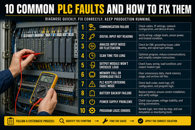
PLC faults rarely come out of nowhere. Most problems fall into a handful of categories—power issues, communication breakdowns, wiring errors, and noise interference. A systematic approach, a multimeter, and understanding of the specific platform's diagnostic tools will resolve the majority of issues without part replacement.
Document every fault, the symptoms observed, and the resolution. Build an internal knowledge base. This is the fastest path to reducing mean time to repair across your facility.
Q: Should I always replace a faulty PLC module?
A: Not necessarily. Many module "failures" are wiring, configuration, or power issues. Always troubleshoot before replacing. Modules can sometimes be repaired by the manufacturer or third-party service providers.
Q: How often should I backup PLC programs?
A: Every time a program change is made. Additionally, perform quarterly archival backups stored in a separate location. Label backups with date, program version, and machine ID.
Q: Can a PLC be damaged by voltage spikes?
A: Yes. Transient voltage suppressor (TVS) diodes and proper grounding are the first line of defense. Install surge protection on power feeds and communication lines. Regular power conditioning pays for itself quickly in industrial environments.
Q: What is the typical lifespan of a PLC?
A: With proper environment and maintenance, PLCs routinely operate 15-20 years. CPU modules and I/O cards may require component-level replacement as electrolytic capacitors age.
Q: Should I keep spare PLC modules on hand?
A: For critical machines, yes. Keep at minimum one spare CPU, one spare power supply, and key I/O modules. For non-critical applications, establish a service agreement with your distributor for 24-48 hour replacement.
· Allen Bradley PLCs — ControlLogix, CompactLogix, MicroLogix
· Siemens PLCs — S7-1500, S7-1200
· PLC I/O Modules — Digital and analog input/output modules
· VFDs — Variable frequency drives for motor control

Please read on, stay posted, subscribe, and we welcome you to tell us what you think.


Sitemap | Blog | XML | Privacy Policy
In addition, with your permission, we want to place cookies to make your visit anointeraction with slOC more personal. For this we use analytical and advertisingcookies. With these cookies we and third parties can track and collect yourinternet behawior inside and outside super-instrument.com. With this we and third parties adapt super-instrument.com and advertisementsto your interest. By clicking Accept you agree to this. If you decline, we only usethe necessary cookies and you unfortunately will not receive any personalizedcontent. Please visit our Cookie policy for more information or to change yourconsent in the future.
Accept and continue Decline cookies