
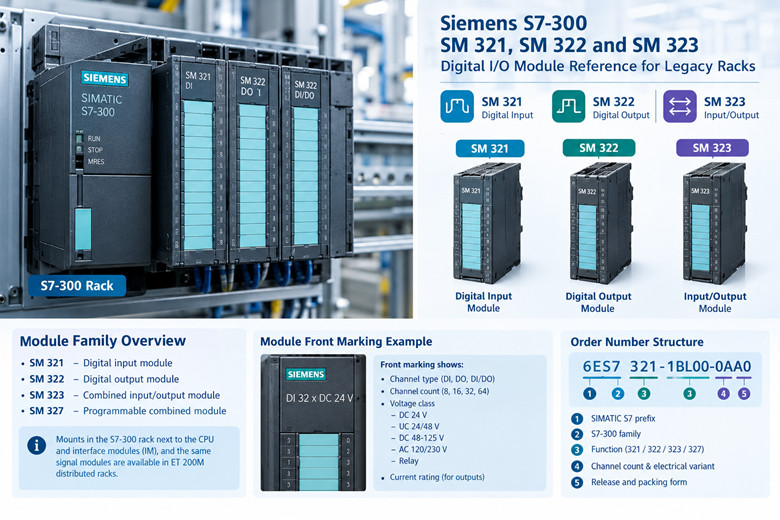
Siemens S7-300 SM 321, SM 322 and SM 323: A Digital I/O Module Reference for Legacy Racks
The S7-300 digital I/O families are SM 321 for inputs, SM 322 for outputs, and SM 323 for combined input/output. SM 327 is the programmable combined module. They mount in the S7-300 rack next to the CPU and the interface modules (IM), and the same signal modules appear in ET 200M distributed racks. Siemens states the S7-300 and ET 200M families are available until 2033. That places these modules in a long spare-parts period, not a discontinued one. This is a reference for the module you are trying to identify, match, or replace.
Siemens order numbers for these modules follow a stable pattern. Read them left to right.
· 6ES7 is the SIMATIC S7 prefix.
· 3 identifies the S7-300 family.
· The next digit groups the function: 321 for digital input, 322 for digital output, 323 for combined digital input/output, 327 for programmable combined.
· The following block encodes channel count and electrical variant.
· The suffix after the final hyphen carries the release and packing state, for example 0AA0.
The module markings on the front carry the same information in plain language. A typical string reads "DI 32 x DC 24 V" or "DO 16 x AC 120/230 V". Read the channel type first (DI, DO, or DI/DO), the count second (8, 16, 32, 64), the voltage class third (DC 24 V, UC 24/48 V, DC 48-125 V, AC 120/230 V, relay), then the current rating for outputs.
The variant suffix matters. The same channel count and voltage can exist in ordinary, High Speed, isolated, and diagnostic versions. These are not interchangeable in a rack that relies on the features of one variant.
Order numbers are printed on the type plate on the side of the module. When the front marking is worn, the type plate is the authoritative source. Pull the module to read it. Do not identify a module by its front label alone.
The final digits of the order number carry the release and the packing form. Two modules with the same function and the same electrical data can sit on different release states. For a like-for-like replacement, match the full order number when the exact part is available. When the exact part is not available, match the function and the electrical data, then confirm the pin assignment in the module data manual before you move wiring.
Channel addresses are not part of the order number. They are assigned by the slot in STEP 7 hardware configuration. The same module in a different slot carries different addresses. Record the addresses before you remove a module.
SM 321 modules read field signals into the CPU. The large channel counts use 40-pin front connectors. The small AC and special-voltage modules use 20-pin front connectors. Read the order number on the module before ordering a replacement.
· DI 64 x DC 24 V, sinking and sourcing selectable: 6ES7321-1BP00-0AA0.
· DI 32 x DC 24 V: 6ES7321-1BL00-0AA0.
· DI 16 x DC 24 V: 6ES7321-1BH02-0AA0.
· DI 16 x DC 24 V High Speed: 6ES7321-1BH10-0AA0.
· DI 16 x UC 24/48 V: 6ES7321-1CH00-0AA0.
· DI 16 x DC 48-125 V: 6ES7321-1CH20-0AA0.
· DI 16 x AC 120/230 V: 6ES7321-1FH00-0AA0.
· DI 8 x AC 120/230 V: 6ES7321-1FF01-0AA0.
· DI 8 x AC 120/230 V, isolated: 6ES7321-1FF10-0AA0.
The DC 24 V modules are the common workhorse inputs. The 32-channel module, 6ES7321-1BL00-0AA0, occupies two front connectors at 40 pins each and covers a dense field of limit switches, proximity sensors, and dry contacts.
The High Speed variant, 6ES7321-1BH10-0AA0, exists for input filtering and edge evaluation that the standard 16-channel module cannot match. The filter time on the standard module limits the shortest signal it will register. If an application counts fast pulses or catches short events, the High Speed module is the correct part, and the standard module is not a substitute.
The UC 24/48 V module, 6ES7321-1CH00-0AA0, accepts either AC or DC in the 24 to 48 volt band. This is a legacy interface module for mixed signal environments. The DC 48-125 V module, 6ES7321-1CH20-0AA0, covers higher DC control voltages. The AC 120/230 V modules, 6ES7321-1FH00-0AA0 at 16 channels and 6ES7321-1FF01-0AA0 at 8 channels, read direct AC control circuits. The isolated 8-channel AC variant, 6ES7321-1FF10-0AA0, adds channel isolation for circuits that must not share a reference.
Input modules carry no output current rating. The selection drivers are voltage class, channel count, filter behavior, and isolation.
Input modules support both sinking and sourcing field devices through the terminal wiring on the qualifying parts. The 64-channel DC 24 V module, 6ES7321-1BP00-0AA0, supports sinking and sourcing selectable at the connector. The other DC input modules accept the common field-device wiring for their class, and the reference manual carries the per-module wiring rule.
The High Speed input module evaluates edges with a shorter filter and can register pulses that the standard module misses. Confirm the required pulse width against the module data before you rely on a standard part.
Wire length and cable routing affect input behavior in a noisy panel. Keep signal cables separated from drive and contactor cables. The input threshold and the filter time in the module data decide whether a long or noisy run holds a stable signal.
Each input module has a channel group structure. The group determines the number of channels that share a reference. Read the group layout in the module data before you combine field circuits on one module.
SM 322 modules drive field loads from the CPU. Current per channel and total current per group decide what a module can switch. The relay module has no DC semiconductor element and switches a different class of load.
· DO 64 x DC 24 V / 0.3 A, sourcing: 6ES7322-1BP00-0AA0.
· DO 64 x DC 24 V / 0.3 A, sinking: 6ES7322-1BP50-0AA0.
· DO 32 x DC 24 V / 0.5 A: 6ES7322-1BL00-0AA0. Total current 4 A per group, 16 A per module.
· DO 32 x AC 120/230 V / 1 A: 6ES7322-1FL00-0AA0.
· DO 16 x DC 24 V / 0.5 A: 6ES7322-1BH01-0AA0.
· DO 16 x DC 24 V / 0.5 A High Speed: 6ES7322-1BH10-0AA0.
· DO 16 x AC 120/230 V / 1 A: 6ES7322-1FH00-0AA0.
· DO 8 x DC 24 V / 2 A: 6ES7322-1BF01-0AA0.
· DO 8 x DC 24 V / 0.5 A with diagnostics interrupt: 6ES7322-8BF00-0AB0.
· DO 8 x relay, AC 230 V / 5 A: 6ES7322-1HF10-0AA0.
· DO 8 x DC 48-125 V / 1.5 A: 6ES7322-1CF00-0AA0.
· DO 8 x AC 120/230 V / 2 A: 6ES7322-1FF01-0AA0.
The 32-channel DC module, 6ES7322-1BL00-0AA0, is the dense DC output workhorse. It is rated 0.5 A per channel with a group total of 4 A and a module total of 16 A. The 64-channel module, 6ES7322-1BP00-0AA0, drops to 0.3 A per channel to fit twice the channels into the same current budget. The sinking version of that same module, 6ES7322-1BP50-0AA0, returns load current to the module instead of sourcing it.
Sourcing and sinking are not cosmetic. A sourcing output supplies positive voltage to the load. A sinking output pulls the load low. The field wiring and the commons decide which one a panel needs. Order the wrong one and the module will not drive the load as wired.
The 8-channel DC 24 V / 2 A module, 6ES7322-1BF01-0AA0, carries the highest DC per-channel current in the family. Use it for contactors, solenoids, and small brakes that exceed the 0.5 A channel rating of the standard modules. The diagnostic variant, 6ES7322-8BF00-0AB0, adds diagnostics interrupt reporting at 0.5 A per channel for circuits where the CPU must see a fault.
The relay module, 6ES7322-1HF10-0AA0, is the one to pick for AC loads, mixed AC/DC loads, and circuits that need true isolation. It switches AC 230 V at 5 A per contact. Relay contacts wear with switching cycles, so cycle count and load type decide relay life.
The 48-125 V DC module, 6ES7322-1CF00-0AA0, and the AC 120/230 V modules, 6ES7322-1FH00-0AA0 at 1 A and 6ES7322-1FF01-0AA0 at 2 A, cover direct control of AC and higher-DC circuits without an interposing relay.
Inductive loads need attention on semiconductor outputs. Contactors, solenoids, and valves generate a turn-off voltage spike. The module data lists the switching capacity and the surge current for each output module. An inductive load that exceeds the channel rating can destroy a semiconductor output over time. Use an interposing relay or the relay output module where the load is inductive and large.
The total current the module can carry is a thermal limit, not purely an electrical one. The 32-channel DC output module is limited to 4 A per group and 16 A per module. Spread the load across groups so no single group carries more than its limit. The module data states the group boundaries.
Bulb loads and capacitive loads draw a much higher inrush current than their steady rating. Read the switching capacity for each module before you connect a capacitive load. The relay output module handles different load types than a semiconductor module at the same voltage class.
Output modules group their channels into commons. The group count and the number of channels per group decide how the load commons are organized at the front connector. Match the field wiring to the group layout of the replacement module.
The combined modules put inputs and outputs on one module. They save slots in a rack that has run out of positions.
· SM 323 DI 16 / DO 16 x DC 24 V / 0.5 A: 6ES7323-1BL00-0AA0.
· SM 323 DI 8 / DO 8 x DC 24 V / 0.5 A: 6ES7323-1BH01-0AA0.
· SM 327 DI 8 / DO 8 x DC 24 V / 0.5 A, programmable: 6ES7327-1BH00-0AB0.
The 16/16 module, 6ES7323-1BL00-0AA0, is the dense combined part. It presents 16 DC 24 V inputs and 16 DC 24 V / 0.5 A outputs in one housing. It uses 40-pin front connectors for the input and output sides.
The 8/8 module, 6ES7323-1BH01-0AA0, is the small combined part for racks with light I/O and limited slot space.
The SM 327 programmable module, 6ES7327-1BH00-0AB0, carries 8 inputs and 8 outputs at DC 24 V with 0.5 A outputs. It is programmable, which means its channel behavior is set in the project rather than fixed in the hardware. It belongs to the earlier programmable signal module line. Treat it as its own part when replacing. A standard SM 323 with the same channel count does not carry the programmable behavior.
Combined modules reduce slot count. They also reduce the flexibility of the rack: a failed input side takes the output side offline with it, and the channel counts are fixed pairs.
Substitution is decided by a short list of hard electrical facts, not by channel count alone.
Voltage class. A DC 24 V module cannot replace an AC 120/230 V module. The input threshold and output switching element are built for the rated class. AC modules detect and switch AC; DC modules detect and switch DC. The UC 24/48 V input module is the exception that accepts both, and it is the only cross-class input part listed here.
Current per channel and per group. Output modules are limited per channel and per group. The 32-channel DC output module allows 0.5 A per channel with a 4 A group limit and a 16 A module limit. Replacing it with the 64-channel module, 6ES7322-1BP00-0AA0, halves the per-channel rating to 0.3 A and tightens the total budget. A load that ran on the 32-channel part may exceed what the 64-channel part will switch. Match the total group current, not just the number of channels.
Sourcing versus sinking. These are separate order numbers within the same channel count. The 64-channel DC output exists in both forms. Wiring built for one will not drive the load correctly on the other.
Isolation. The isolated input module, 6ES7321-1FF10-0AA0, exists where channel and circuit isolation is required. A non-isolated module is not a direct substitute where isolation is part of the design.
Filter and speed variant. Standard modules and High Speed modules share channel counts. The standard module will not meet the timing of an application that was designed around the High Speed part. Identify the variant suffix before substituting.
Front connector width. This is the substitution trap that costs time on site. A 40-pin module needs a 40-pin front connector. A 20-pin module needs a 20-pin front connector. The connector carries the field wiring, and it is a separate article from the module. When you replace a module, you either reuse the existing front connector or you move the wiring. Whether the old connector fits the new module depends on the module family and the pin assignment.
Reuse the front connector only when the new module is the same order number or an equivalent with the same pin assignment. When the pin assignment changes, the old wiring pattern becomes a fault. Move the wiring with the pin table of the new module in hand. Do not assume that a visually similar module shares the pinout of the failed one.
Rack width and slot. All S7-300 signal modules are single-width except where a module covers two connectors. The 64-channel and 32-channel parts use two 40-pin connectors. Confirm the rack position can carry the connectors and the cable routing.
Backplane communication. Signal modules talk to the CPU over the backplane bus. The CPU reads and writes the module through its assigned addresses. A replacement module of the same type uses the same communication and needs no program change. A different module type may change the data layout and require a configuration change.
Load voltage supply. DC output modules need a load voltage supply at the module terminals. The module data states the rated load voltage range for each part. Confirm the panel supply sits inside that range before you power a replacement. AC output modules take their load voltage from the field circuit.
Potential separation. The isolation between the field side and the backplane bus is a stated value per module. Where the design relies on that separation, match it. The isolated input module, 6ES7321-1FF10-0AA0, is the part to reach for when channel-to-channel or field-to-bus separation is required.
Module diagnostics. Some modules report module-level diagnostics to the CPU, and some do not. The diagnostic output module, 6ES7322-8BF00-0AB0, reports at the module and channel level. A standard module does not. If the program reads diagnostic data from the module, the replacement must support the same diagnostics.
Worn front marking is common on modules that have run for years in a hot panel. Two sources settle the identity.
The type plate on the side of the module carries the full order number. Pull the module and read it. The order number on the type plate is the order number to order. Order numbers do not change between the front label and the type plate.
STEP 7 hardware configuration carries the module identity as the CPU sees it. Open the project, select the rack, and read the slot. The hardware catalog stores the order number and the module type for each slot. When the physical module and the configured slot disagree, the CPU reports a module mismatch. Read the configured order number from the slot and match it against the physical type plate.
The slot in STEP 7 also tells you the channel addresses. Record the address range before you pull a module. The addresses stay with the slot, so a replacement with the same module type needs no address change in the program.
When the type plate is also unreadable, work from behavior. Count the terminals. Read the front connector wiring. Match the voltage class at the field terminals. Match the channel count to the field devices. Then choose the order number that fits, and confirm against the STEP 7 slot.
Read the module data manual for pin assignments. The S7-300 Automation System Module Data reference, Siemens order number 6ES7398-8FA10-8BA0, document A5E00105505, covers the pin tables. Editions through 05/2022 exist. Use the edition that matches the module generation in the rack.
For sourcing these modules, Siemens automation spare parts covers the legacy signal module range. For the wider rack hardware, PLC hardware covers the adjacent parts. The module data above is the same reference a maintenance engineer reads at the panel.
Can I replace an SM 321 DI 16 x DC 24 V with a DI 32 x DC 24 V module?
Not as a direct swap. The channel count differs, the addresses differ, and the connector width may differ. The 16-channel module may use a 20-pin connector while the 32-channel part uses 40-pin. Match the order number first, then confirm the addresses and the connector.
Can I use a sourcing output module where a sinking one was installed?
No. The load path is reversed. The field wiring and the load commons are built for one direction. Use the same sourcing or sinking form, matched by order number.
Does the 64-channel DI or DO module fit the same slot as a 32-channel module?
Physically it may occupy the same width, but it needs two 40-pin front connectors. Confirm the rack wiring and cable routing before you commit to the swap.
What replaces the 6ES7322-1BH01-0AA0 if it is not available?
Read the order number and the type plate. Then match voltage class, channel count, current per channel, sourcing or sinking, and connector width. The 16-channel DC 24 V output at 0.5 A has related variants, including the High Speed part, and they are not identical in behavior. Do not substitute on channel count alone.
Can a relay output module replace a DC semiconductor output module?
For many DC loads, yes, within the relay contact rating and the switching cycle budget. The relay is rated AC 230 V at 5 A per contact in the module listed here. Relay contacts wear with cycles, so count the switching frequency before you choose it. For fast DC switching, the semiconductor module is the correct part.
Do I need to change the program when I replace a module with the same order number?
No. The addresses stay with the slot. A same-order replacement needs no address change. Keep the front connector wiring matched to the pin assignment.
What does the diagnostics interrupt on 6ES7322-8BF00-0AB0 give me?
Module and channel diagnostics reported to the CPU. If the program evaluates those diagnostics, a standard module that lacks them is not a substitute. The CPU will see the module but not the diagnostics the program expects.
How long will these modules be available?
Siemens states the S7-300 and ET 200M families are available until 2033. That is the manufacturer position. In practice, individual order numbers thin out over time, which is why matching the exact part matters.
Where do I find the pin assignment for a module before I move wiring?
The S7-300 Automation System Module Data reference, 6ES7398-8FA10-8BA0, document A5E00105505. Read the edition that fits the module generation. The pin table in the manual is what governs the connector wiring.
Is the SM 327 the same as the SM 323 with more channels?
No. The SM 327 is a programmable module. Its channel behavior is set in the project. The SM 323 is fixed-function combined I/O. Match the order number.
How do I tell a 16-channel module from a 32-channel module when the label is gone?
Count the front connector pins. A 20-pin connector points to a lower channel count in the small module classes. A 40-pin connector points to 16 or 32 channels depending on the part. Then read the type plate and confirm against the STEP 7 slot.
Can I mix a 40-pin module and a 20-pin module in the same rack?
Yes. The rack carries modules of different widths and connector sizes. Each module keeps its own front connector and its own pin assignment. The rack position and the address range are what tie it to the program.
What happens if I install a module with a different order number in a configured slot?
The CPU compares the physical module against the configured type. When they disagree, the CPU reports a module mismatch or a configuration error. The slot may not go into run. Match the configured order number from the STEP 7 slot.
Do I need the front connector to order a module?
The front connector is a separate article. When you order a replacement module, confirm whether the existing connector fits. If the pin assignment differs, order the connector that matches the new module and move the wiring with the pin table in hand.
Are the AC 120/230 V modules interchangeable between the 8-channel and 16-channel parts?
No. They differ in channel count and connector width. Match the order number and confirm the field wiring against the pin table.
---------------------------------------------------------
🏢 About TZ Tech
TZ Tech is a leading supplier of industrial automation, electrical, instrumentation, and telecommunications components. We specialize in sourcing ready-to-ship distributor stock, allowing us to offer highly competitive pricing and short lead times. Thanks to our extensive inventory, we can even source rare and discontinued parts that are hard to find elsewhere.
🛡️ Our Quality Commitment
We understand that quality is your top priority. Every component undergoes a strict screening and inspection process so you can buy with absolute confidence. For legacy or discontinued parts, we believe in complete transparency and will always provide an honest, accurate report on the product's condition. Plus, all brand-new parts come backed by a full 1-year warranty.
✉️ Get in Touch
Have a project or a part you need? Send us your inquiry today! Our team is dedicated to providing a fast response within 6 hours (excluding weekends).


Please read on, stay posted, subscribe, and we welcome you to tell us what you think.


Sitemap | Blog | XML | Privacy Policy
In addition, with your permission, we want to place cookies to make your visit anointeraction with slOC more personal. For this we use analytical and advertisingcookies. With these cookies we and third parties can track and collect yourinternet behawior inside and outside super-instrument.com. With this we and third parties adapt super-instrument.com and advertisementsto your interest. By clicking Accept you agree to this. If you decline, we only usethe necessary cookies and you unfortunately will not receive any personalizedcontent. Please visit our Cookie policy for more information or to change yourconsent in the future.
Accept and continue Decline cookies