
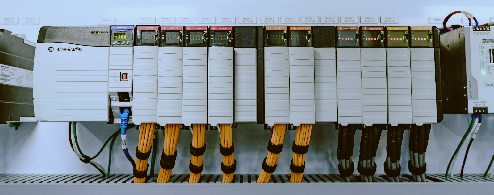
Siemens S7-300 Communication Processors: CP 342-5, CP 343-1 and CP 343-1 Lean
A communication processor occupies a physical slot in the S7-300 rack but does none of the control work. Its entire function is to move data between the CPU and a network. Understanding that separation is the first step in diagnosing why a CP will not open its connection.
The SIMATIC S7-300 was designed around a modular principle. A rail holds the power supply, the CPU, and a set of signal modules. The CPU owns the user program, the process image, and the backplane bus activity that ties the rack together. Every other module answers to the CPU.
A communication processor is an exception to that pattern in one specific respect. It does not evaluate the user program, and it does not read inputs or drive outputs in the ordinary sense. What it does is own an independent interface to an external network, with its own firmware, its own memory, and its own connection management. The CPU treats the CP as a partner module that exchanges data blocks and status words across the backplane.
That architectural boundary governs almost everything a maintenance engineer needs to know about these modules. Connection limits are CP limits, not CPU limits. LED behavior is CP behavior. Firmware version is a CP property. When communication fails while control continues to run, the fault is almost always on the CP side of the boundary.
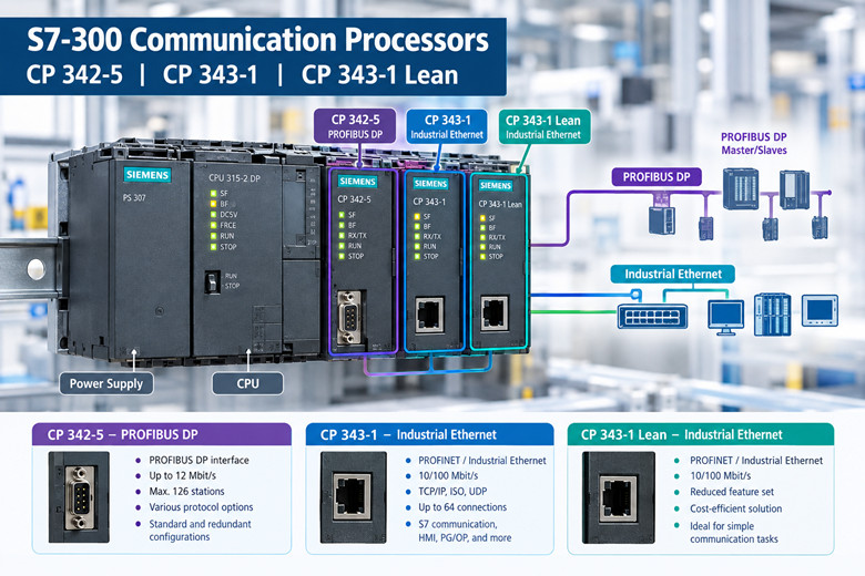
What a communication processor does in an S7-300 rack
A CP is a bus participant on two sides at once. On the rear side it communicates with the CPU over the backplane bus, requesting and returning data through a defined interface of data blocks, parameter assignment, and diagnostic records. On the front side it drives one or more physical ports toward an external network, whether that network is PROFIBUS DP, Industrial Ethernet, or a proprietary serial link in older families.
The arrangement means the CP can fail without stopping the plant process. If a CP loses its network, the CPU continues to execute its program and continues to control the machine. Only the data exchange across the failed path stops. This is a design feature, and it is also the reason communication faults can go unnoticed until an operator reports that a supervisory system has lost its values.
Data exchange between CPU and CP is not instantaneous. It is a defined cycle of requests and confirmations, gated by the scan of the backplane and by the connection state on the network side. When a supervisor reads a value too soon after a change, that value may still reflect the previous exchange. Understanding the exchange model prevents misdiagnosis of what is actually a timing artifact rather than a fault.
Each CP carries a parameter assignment that the hardware configuration tool generates and downloads. That assignment defines addresses, connection endpoints, protocol options, and diagnostic behavior. A CP with no valid assignment will not come online, even though its LEDs may show power. Configuration is therefore part of the hardware, not an optional layer above it.
A CP also carries its own firmware, which is separate from the CPU operating system. Firmware version determines which functions are available. The same order number can be delivered with different firmware across the years, and a replacement CP of the correct order number but a different firmware revision may behave differently from the unit it replaces.
The practical consequence of all of this is a diagnostic sequence that follows the boundary. First establish whether the CPU and CP are talking across the backplane. Then establish whether the CP has a valid network interface. Then establish whether the network peer is answering. Only after those three layers are resolved does it make sense to examine the application program.
The CP families you will meet: PROFIBUS, Industrial Ethernet, and the integrated port
Communication processors for the S7-300 fall into three broad categories, and the category determines the network the module serves.
The first category is the PROFIBUS DP communication processor, represented by the CP 342-5. This family gives a CPU a PROFIBUS DP interface that runs independently of the CPU's own integrated DP port. It can act as a DP master or as a DP slave, and it is used when a rack needs a second PROFIBUS line, a denser DP segment, or a DP interface that is isolated from the CPU's own port for diagnostic or architectural reasons.
The second category is the Industrial Ethernet communication processor, represented by the CP 343-1 and CP 343-1 Lean. These modules connect the rack to Ethernet networks and support a range of protocols, from classic S7 communication across ISO and TCP/IP transport to PROFINET IO roles. This is the family that dominates modern replacement demand, because Ethernet is the network that most supervisory, historian, and engineering systems now use.
The third category is the integrated port, which is not a separate module at all. Many S7-300 CPUs ship with an onboard PROFIBUS DP port, an onboard PROFINET port, or both, depending on the CPU type. The integrated port is not a CP, it is a CPU function. It shares the CPU's resources, and it appears in the hardware configuration as part of the CPU rather than as a separate slot entry.
The distinction matters for counting and for fault isolation. A rack with an integrated Ethernet port plus one CP 343-1 has two independent Ethernet interfaces, and a failure on one does not necessarily affect the other. A rack relying only on an integrated port has no CP slot to inspect when the network fails, and the diagnostic path moves inside the CPU.
It also matters for vendor compatibility and for the age of the design. The CP 343-1 family is the module that was specified when a plant needed Ethernet connectivity in a rack whose CPU had no onboard Ethernet, or when the onboard port was already committed to another role. Many legacy installations were built precisely on that basis, and those are the racks now driving spare-part purchases.
A fourth category, the serial communication processor, existed in the earlier S7-300 line, with order numbers in the 6GK7 342-5 and 6ES7 340 and 6ES7 341 ranges depending on function. Serial CPs are outside the scope of this article, but a maintenance engineer inventorying a rack should recognize that not every CP in a legacy installation is a network module. The order number on the label settles the question faster than any assumption about the front panel.
Across all categories, the operating principle stays the same. The module owns a network interface, the CPU owns the program, and the backplane carries the data between them. That principle holds whether the external medium is a shielded two-wire bus, a twisted-pair Ethernet cable, or a fiber segment behind a converter.
CP 343-1 and CP 343-1 Lean: reading the order number and the feature split
The CP 343-1 in the version covered here carries order number 6GK7343-1EX30-0XE0. That code decomposes into a family prefix, a variant digit, a version field, and a delivery field, and each field is worth reading carefully before any purchase or replacement decision.
The part in use in this article connects a SIMATIC S7-300 to Industrial Ethernet through ISO and TCP/IP. The module includes an integrated two-port switch built on the ERTEC 200 communication chip, and it presents two RJ45 ports at 10/100 Mbps. It can function as a PROFINET IO controller or as a PROFINET IO device, depending on how the configuration assigns it.
Its communication function set covers S7 communication, fetch and write services, send and receive over RFC1006, multicast, DHCP, and NTP time synchronization. In practical terms, that combination supports supervisory data collection, engineering access, time synchronization across a plant, and peer-to-peer communication between controllers, all through one module.
Siemens lists up to eight communication or function modules per CPU as a planning limit for this family, and states that the exact number depends on the CPU type. The limit is a CPU property expressed as a module count, so a CPU with a larger communication budget can carry more CPs than a compact CPU with a smaller one. The number that applies to a specific rack must be read against that rack's CPU, not assumed from the CP datasheet alone.
The CP 343-1 Lean carries order number 6GK7343-1CX10-0XE0. The Lean label signals a reduced function set at a lower cost, and the reduction is concentrated in the protocol and connection profile rather than in the physical interface. A Lean module still presents two RJ45 ports at 10/100 Mbps, so the cabling and switch topology at the cabinet are the same as for the full CP 343-1.
The Lean feature split is specific. It supports TCP/IP and UDP, RFC1006 send and receive, fetch and write services, and S7 communication in the server function. It can act as a PROFINET IO device. It does not carry the PROFINET IO controller capability of the full module, and it does not carry the full module's multicast, DHCP, and NTP function set.
The connection counts differ in a way that is decisive for design. The CP 343-1 Lean supports a maximum of eight SEND/RECEIVE connections and a maximum of four S7 connections, with up to twelve active connections when operating in multi-protocol mode. The full CP 343-1 does not publish the same reduced ceilings, because it is intended for racks that need broader simultaneous participation.
Written as a plain comparison rather than a table, the split reads as follows. Full CP 343-1: ISO and TCP/IP, PROFINET IO controller or IO device, integrated two-port switch, S7 communication, fetch/write, RFC1006 send/receive, multicast, DHCP, NTP. Lean CP 343-1: TCP/IP and UDP, RFC1006 send/receive, fetch/write, S7 communication as server, PROFINET IO device only, two RJ45 ports, eight SEND/RECEIVE connections, four S7 connections, twelve active connections in multi-protocol mode.
The selection rule follows directly from those lists. If the rack must control PROFINET IO devices, the full CP 343-1 is required. If the rack only needs to be an IO device on someone else's PROFINET controller, or only needs supervisory data exchange and engineering access, the Lean module is sufficient and was priced accordingly.
Both modules sit under product cancellation or spare-part status on Siemens's own product pages for the article numbers listed here. That status does not mean the modules stop working, and it does not mean support for existing installations ends. It means new production supply is governed by spare-part availability rather than by ongoing series manufacture.
Order-number literacy is the single most useful skill when sourcing either module. The 6GK7343 prefix identifies the Ethernet communication processor family. The following digits distinguish variant and version, and the final block identifies the delivery form. Two modules that look identical on the front panel can carry different order numbers with different firmware floors and different function sets. The label on the module, not the appearance of the module, is authoritative.
Where the exact code on a module does not match any code listed in this article, the correct action is to read the complete order number from the module label and search against that string. Siemens issued multiple versions across the production life of the family, and the version field is the part most often overlooked.
CP 342-5 and the PROFIBUS DP path
The CP 342-5 is the PROFIBUS DP communication processor for the S7-300. Its order number begins 6GK7342, and the exact code must be read from the module label because several versions exist across the production life of the type.
Its role is to give the rack a PROFIBUS DP interface that operates off the CPU. The phrase off the CPU is the operative one. The CP performs the DP protocol handling in its own processor, using its own memory, and exchanges the resulting data with the CPU across the backplane. The CPU's own scan is not spent on DP telegram processing.
A CP 342-5 can be configured as a DP master or as a DP slave. As a master, it polls its assigned DP slaves and maintains the input and output images that the CPU reads and writes. As a slave, it answers the polling of an external DP master, presenting the rack's data to a network it does not control.
The master role is the more common in retrofit and expansion work. A plant adds a new DP segment, or splits an existing segment to shorten cable runs and reduce fault exposure, and the CP 342-5 provides the second master without disturbing the CPU's integrated port or its program.
The slave role appears where a legacy S7-300 rack must present data to a newer controller, or where one S7-300 rack must serve as a subordinate station to another. In the slave configuration the CP is configured as a distributed I/O station, and the rack behaves toward the external master in the manner of an ET 200 station.
Because the DP work is performed off the CPU, the CP 342-5 also isolates DP faults from the control program. A broken DP segment, a lost slave, or a bus short affects the CP and the affected segment, while the CPU continues to control whatever else the rack governs. The diagnostic records for the fault live in the CP and are read through the hardware configuration tool.
The DP segment served by a CP 342-5 is bounded by the standard PROFIBUS rules. Segment length depends on the transmission rate, the cable type, the number of repeaters, and the loading of the bus. These rules apply to a CP-driven segment exactly as they apply to a CPU-driven one, because the CP is a conforming DP master or slave with the same physical layer behavior.
For sourcing, the practical instruction is the same as for the Ethernet family. Read the complete order number from the module label and treat the full string as the part identity. CP 342-5 versions differ in firmware and in supported function set, and a replacement must be matched to the installed version's requirements as well as to its function. Buyers keeping a legacy S7-300 rack in service should record the full string at the time of inventory, while the module is still readable in the rack, rather than at the moment of failure when the line is down.
How many modules and connections a CPU will actually carry
Two separate limits govern a rack's communication capacity, and confusing them produces designs that will not compile or connections that will not open.
The first limit is the number of communication and function modules a CPU will accept. Siemens states a planning figure of up to eight such modules per CPU for the CP 343-1 family, and states that the exact figure depends on the CPU type. This is a hardware configuration limit. Exceed it and the configuration tool will reject the assignment.
The second limit is the number of simultaneous connections a single CP will carry. This is a module limit, held inside the CP's own firmware and memory. For the CP 343-1 Lean the published ceilings are eight SEND/RECEIVE connections, four S7 connections, and up to twelve active connections in multi-protocol mode. The full CP 343-1 does not carry the same reduced ceilings, which is the point of paying for the full variant.
A rack's total communication capacity is therefore not a single number. It is a function of which CPU is present, how many CPs the CPU accepts, and which CP variants are fitted. Two racks built on the same rail with the same number of slots can carry very different connection counts depending on those three variables.
Connection counts are consumed by roles, not by cable count. A single supervisory system that opens S7 connections for data collection consumes S7 connections. Peer controllers opening configured S7 communication consume S7 connections. Send and receive services over RFC1006 consume SEND/RECEIVE connections. Multi-protocol operation can raise the aggregate active count while the per-protocol ceilings still apply.
The practical test is inventory and arithmetic. List every system that opens a connection to the rack, classify each by protocol, and add the requirements against the fitted CP's published ceilings. Where the sum exceeds a ceiling, the rack does not have a fault, it has a design limit, and the remedies are a different CP variant, an additional CP, or a redistribution of connections across available interfaces.
The integrated port changes the arithmetic. Where a CPU has an onboard Ethernet or PROFINET port, that port carries its own connection capacity independent of any CP. A rack with an onboard port plus a CP 343-1 Lean may meet its total connection demand even though the Lean ceilings alone appear tight, because the onboard port absorbs part of the load.
Knowledge of which interface carries which connection is what allows a rack to be modified without redesign. When a new historian or a new supervisory node is added, the first question is which interface it will attach to, and the second is whether that interface has headroom against its published ceiling.
The module count limit is the harder constraint to work around, because adding a CP consumes a slot. Where a CPU accepts a limited number of communication modules and those slots are already occupied, an additional CP is not available as a remedy, and the solution moves to a higher-capacity CPU or to consolidation of connections onto existing modules.
Reading the LEDs when a CP will not come online
LED diagnostics on a CP follow the same layered logic as the architecture. The front panel reports the state of the module, the state of the backplane interface, and the state of the network interface, and reading them in that order narrows the fault to a layer before any software is opened.
The power and run indicators establish that the module is alive. A CP with no illumination at all has a supply or seating problem, which is a cabinet issue rather than a network issue. The first physical checks are that the module is seated correctly on the rail, that the backplane connector is engaged, and that the rack's power supply is delivering the required voltage to the module row.
The bus fault indicator, where present, reports the state of communication with the CPU across the backplane. An illuminated fault light with no network activity points at configuration or at the CPU side of the boundary, not at the cable. The common causes are a configuration that was created but not downloaded, a configuration that does not match the physical slot arrangement, or an address conflict within the rack.
The network indicators report the state of the external interface. On the CP 343-1 family these are associated with the two RJ45 ports and with link and activity state. A port with no link has no electrical connection to a partner, which is a cabling or switch issue. A port with link but no activity has a live physical connection and no traffic, which moves the investigation to addressing, protocol configuration, or the peer device.
The diagnostic buffer and the module diagnostic records carry more detail than the LED panel can. The hardware configuration tool reads these records and reports specific fault conditions, including configuration errors, connection failures, and hardware faults. When the LEDs point at the backplane or at a connection, the diagnostic record identifies the specific cause.
A CP that will not open its connection frequently has a valid configuration that does not match reality. The parameter assignment may name a peer address that has changed, a protocol option the peer does not support, or a connection type that exceeds the module's ceiling. The LEDs will show link and may show activity, while the connection itself does not establish, because the fault is in the assignment rather than in the wire.
Firmware and function set mismatch is a separate class of fault that LEDs will not reveal. Where a function was configured that the installed firmware does not support, the module may reject the configuration or fail at connection establishment. Reading the firmware version from the module and comparing it against the configured function set resolves this class of fault.
Replacement is the last step, not the first. The sequence that saves the most time is physical, then backplane, then network, then configuration, then firmware, and only then hardware. A large share of CPs returned as faulty are found to have a configuration or cabling cause once the layers are worked in order.
Why these modules now sit in spare-part status
The S7-300 was declared discontinued on October 1, 2025, at the PM410 status milestone. The end-of-production-and-sales milestone, PM490, is scheduled for October 1, 2033. Siemens states that the S7-300 and ET 200M families are available as spare parts until 2033.
That timeline places the CP 342-5, the CP 343-1, and the CP 343-1 Lean in a long spare-part period rather than a dead one. Spare-part status means the modules remain available through the vendor's spare-part channel for a defined period, even though series production has ended and the type has been removed from the active catalog.
For a plant running S7-300 racks, the practical meaning of this status is a change in supply behavior rather than a change in function. Existing modules continue to operate and continue to be supported for repair and replacement within the period. New stock arrives through spare-part channels, with the lead times and pricing behavior that channel implies.
The announcement date of October 1, 2025 has a second consequence that matters for planning. Consultants and integrators who specified S7-300 in new designs have moved to current platforms, which means the installed base of S7-300 racks is now a fixed and slowly shrinking population. Spare-part demand comes from that population, and the modules that keep it running are increasingly sourced from specialist suppliers rather than from the original channel alone.
The 2033 milestone sets the planning horizon. A plant that intends to operate S7-300 racks beyond that date should treat the intervening years as the window in which to either lay in adequate spares or plan the migration. The two strategies are not mutually exclusive, and many plants run both at once, stocking critical modules while scheduling replacement of the racks whose processes are most expensive to stop.
The criticality of a CP to a specific plant determines how much of it to hold. A rack whose CP carries only supervisory data may tolerate a CP failure for hours or days. A rack whose CP carries interlock data to another controller may not tolerate it for minutes. The correct spare quantity follows from the process consequence, not from a uniform stocking rule.
Supply for these modules also includes the refurbished and surplus market, which matters because the period until 2033 is long and the installed base is finite. A clean, tested module from a reputable supplier performs the same function as a new one, provided the order number and firmware are matched. Siemens automation spare parts sourced through a specialist can bridge the gap between a failure and the next scheduled shutdown.
The risk to avoid is a mismatch discovered at the moment of failure. A module purchased without confirming the exact order number and firmware may arrive with a function set that does not match the configuration in the PLC program. The cost of that mismatch is a second downtime window, which is the outcome the spare was purchased to prevent.
What to record before you buy a replacement
The single most valuable record is the complete order number read from the module label. For the Ethernet family this begins 6GK7343; for the CP 342-5 it begins 6GK7342. The complete string, including the delivery block, is the part identity. Anything short of the complete string is a guess.
The second record is the firmware version, read from the module through the hardware configuration tool. Firmware determines function set, and a replacement at a different firmware revision may or may not meet the configuration's requirements. Where a downgrade is impossible, the firmware floor becomes a purchase constraint.
The third record is the physical slot position and the rack layout. Slot position is part of the hardware configuration, and a replacement must occupy the same position so that the downloaded configuration continues to match the physical rack. A photograph of the rack with slot numbers visible takes a minute and prevents a class of configuration errors that are tedious to resolve under time pressure.
The fourth record is the network topology attached to the module, including the port usage on a two-port CP. A CP 343-1 or CP 343-1 Lean presents two RJ45 ports, and which port feeds which segment is part of the installation's identity. Recording that mapping allows a replacement to be cabled correctly without rediscovering the topology during a shutdown.
The fifth record is the connection inventory, classified by protocol and checked against the module's ceilings. This record is not needed to order a replacement, but it is needed to confirm that the replacement will carry the existing connection load. Where the load approaches a ceiling, the replacement decision and the capacity decision should be made together.
The sixth record is the CPU type in the rack, because the module count limit is a CPU property. A plant standardizing on a spare CP for several racks should confirm that the chosen module is acceptable in every CPU type among them.
Inventory practice matters as much as the individual records. A plant that records these six items for every CP while the racks are healthy carries a spare-part program, whereas a plant that records them after a failure carries a recovery effort. The difference is measured in hours of downtime, and the cost of the records is measured in minutes.
For racks that carry more than one CP, the records should be kept per module rather than per rack. Two CPs in the same rack can be different variants with different function sets, and a rack-level record will not distinguish them.
The purchase itself is then a matching exercise. Order number matched, firmware floor satisfied, function set confirmed against the connection inventory, and slot position preserved. A replacement meeting those four conditions returns the rack to its prior state without a configuration change, which is the definition of a successful spare-part event for a communication processor.
Where the installed module cannot be matched exactly, because the version is no longer available at any price, the next step is a documented substitution: the highest available version of the same order number, with the configuration's function set checked against the newer firmware, and the connection inventory confirmed against the newer module's ceilings. Substitution is a legitimate path within the spare-part period, provided it is documented rather than improvised.
Buyers building a stock position for legacy S7-300 communication should also value consistency. Holding one variant that matches the most racks is more useful than holding several partial matches, because a spare that fits one rack out of twelve is a liability rather than an asset. The Siemens PLC modules held as stock should be chosen from the recorded order numbers across the plant, weighted by the criticality of the racks they serve.
The final discipline is verification before installation. A replacement module should be read with the hardware configuration tool on the bench where possible, its order number and firmware confirmed against the purchase record, before it is installed into a live rack during a shutdown window. Verification on the bench takes minutes and removes the possibility of discovering a mismatch at the worst moment.
A communication processor occupies a slot but runs none of the program. It owns an interface, a firmware image, a configuration, and a fixed set of connection ceilings. The S7-300 line entered spare-part status on October 1, 2025, with the end-of-production milestone set for October 1, 2033. Between those dates, the racks that remain in service depend on matched spares, and the records kept for the CPs in those racks determine how quickly any failure is resolved. Siemens S7-300 spare parts sourced against a complete order number and a firmware floor are what keep a legacy rack communicating.
🏢 About TZ Tech
TZ Tech is a leading supplier of industrial automation, electrical, instrumentation, and telecommunications components. We specialize in sourcing ready-to-ship distributor stock, allowing us to offer highly competitive pricing and short lead times. Thanks to our extensive inventory, we can even source rare and discontinued parts that are hard to find elsewhere.
🛡️ Our Quality Commitment
We understand that quality is your top priority. Every component undergoes a strict screening and inspection process so you can buy with absolute confidence. For legacy or discontinued parts, we believe in complete transparency and will always provide an honest, accurate report on the product's condition. Plus, all brand-new parts come backed by a full 1-year warranty.
✉️ Get in Touch
Have a project or a part you need? Send us your inquiry today! Our team is dedicated to providing a fast response within 6 hours (excluding weekends).


Please read on, stay posted, subscribe, and we welcome you to tell us what you think.


Sitemap | Blog | XML | Privacy Policy
In addition, with your permission, we want to place cookies to make your visit anointeraction with slOC more personal. For this we use analytical and advertisingcookies. With these cookies we and third parties can track and collect yourinternet behawior inside and outside super-instrument.com. With this we and third parties adapt super-instrument.com and advertisementsto your interest. By clicking Accept you agree to this. If you decline, we only usethe necessary cookies and you unfortunately will not receive any personalizedcontent. Please visit our Cookie policy for more information or to change yourconsent in the future.
Accept and continue Decline cookies