PowerFlex 4, 40 and 70 Drives: Fault Codes, Common Failures, and the Spares That Keep Them Running
Sep 16, 2026
Catalog structure
Read the full catalog string before ordering anything. The prefix gives the family. The remainder gives frame, voltage class, rating and enclosure.
22A = PowerFlex 4.
22B = PowerFlex 40.
22F = PowerFlex 4M.
20A = PowerFlex 70.
20AD = PowerFlex 70.
20AE = PowerFlex 70.
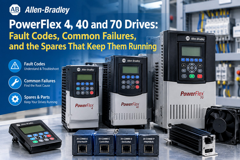
Communication adapters carry the 20-COMM prefix.
20-COMM-E for EtherNet/IP.
20-COMM-C for ControlNet.
20-COMM-D for DeviceNet.
20-COMM-P for PROFIBUS.
Keypads: 22-HIM-A3 and 22-HIM-C2S.
Braking resistors: 20-DR series.
Spare parts for these drives sit under those prefixes only. If a seller quotes you a number that will not cross to one of the prefixes above, stop and verify it. The family prefix is the anchor. Everything downstream depends on it.
Cross-check the frame. A 22B frame C is not a 22B frame A. Same family, different heatsink, different fan, different mounting, different power stage.
The frame decides the fan, the heatsink, the terminal spacing and the board layout. Order by frame, not by family alone. A generic "PowerFlex 40 fan" does not exist. It is a PowerFlex 40 frame-specific fan, and the part number changes with the frame letter.
Legacy stock moves through surplus channels. Numbers get misquoted. Confirm the full string on the drive label against the vendor listing before payment. See the Allen-Bradley range at Allen-Bradley range when you need to match a prefix to a stocked unit.
Electrical classes
Voltage classes appear in the catalog string. Read them there, not from memory.
240 V single-phase.
240 V three-phase.
400 V three-phase.
480 V three-phase.
Power rating bands, stated generally:
PowerFlex 4 covers roughly the 0.2 to 2.2 kW band. Frame dependent.
PowerFlex 40 covers roughly the 0.4 to 11 kW band. Frame dependent.
PowerFlex 70 extends higher. Frame dependent.
These bands are orientation only. Exact kW and HP per frame must be read from the drive's own catalog string and the manual for that frame. Do not size a replacement from the band. Size it from the label.
A published rating table here would be wrong for someone. Frame letters cover multiple ratings across voltage classes, and single-phase and three-phase versions of the same frame do not carry the same kW. The label is the only source that cannot mislead you.
Practically: photograph the label. Note the full catalog string, the input voltage, the output kW or HP, the output current and the enclosure. That photograph is your order form.
If the label is gone, and the machine still runs, you have a problem. Then you trace the motor nameplate FLA and the motor voltage, measure the running current, and pick a frame that covers the FLA with margin. That is the fallback path, not the preferred one.
Single-phase input classes appear on the smaller frames. Three-phase classes dominate above the small band. Do not assume a drive that runs on 240 V three-phase will accept 240 V single-phase. Check the class in the string.
Interfaces
PowerFlex 4 and PowerFlex 40 expose a DSI (Drive Serial Interface) RS-485 port.
PowerFlex 70 uses DPI and 20-COMM adapters for networking.
The DSI port on the 4 and 40 carries serial communication and keypad traffic. Simple, two-wire, and easy to miswire. The 20-COMM adapters on the 70 slide into the drive and give it a network face: EtherNet/IP, ControlNet, DeviceNet or PROFIBUS.
Keypads are removable. A keypad from a PowerFlex 4 moves to another PowerFlex 4 in the same family. Same for the 40 and same for the 70. This is the fastest diagnostic swap you have. Move a known-good keypad onto a dead-display drive and see if the display comes back.
If the display comes back with the swapped keypad, the fault is in the keypad or its contacts. If the display stays dark with a known-good keypad, the fault is in the drive, and the control supply is the first suspect.
A keypad is a terminal, not a permanent fixture. Treat it as a serviceable part and carry one. One 22-HIM-A3 or 22-HIM-C2S on the shelf covers an entire family.
Fault table
Faults latch. These drives do not self-clear. After the cause is corrected, the drive needs an explicit reset.
Reset methods: keypad Stop/Reset key, a digital input programmed to fault reset, or a power cycle. Pick one and use it consistently so the next person knows the sequence.
Fault | Meaning | First checks
F004 | Undervoltage | Input voltage balance, loose line or motor terminations, weak bus capacitors under load
F005 | Overvoltage | Deceleration time against load inertia, regeneration from the load, braking resistor fitted
F007 | Motor Overload | Motor FLA setting against nameplate, mechanical binding, motor temperature
F008 | Heatsink Overtemperature | Blocked or dirty heatsink fins, cooling fan operation, ambient temperature
F013 | Ground Fault | Motor insulation, cable damage, moisture in the motor terminal box
F004 Undervoltage
A DC bus undervoltage trip. The bus fell below the level the drive needs to keep the output stable.
First suspect: input voltage. Measure all three phases under load, not at rest. A sag that only shows when the machine runs is the one that matters.
Second suspect: loose terminations. Line side and motor side. A high-resistance joint drops voltage under current. Tighten, inspect for heat discoloration, replace any lug that looks cooked.
Third suspect: weak bus capacitors. The bus sags under load but holds at light load. This is an age fault, not a wiring fault. See the age section.
Record the code history. If F004 appears only on high-load cycles, the input or the motor circuit is loading the bus beyond what the supply can hold.
F005 Overvoltage
A DC bus overvoltage trip. The bus rose above the level the drive tolerates.
First suspect: deceleration time against load inertia. A high-inertia load pushed to stop too fast dumps energy back into the bus. Lengthen the deceleration ramp until the trip stops.
Second suspect: regeneration from the load. An overhauling load or a driven load that goes faster than command pushes energy back. Gravity loads on hoists and conveyors do this.
Third suspect: no braking resistor fitted. If the application regenerates, a 20-DR series braking resistor is the fix. Without one, the bus has nowhere to dump the energy.
Check whether the drive had a braking resistor option and whether it is still connected. A disconnected or failed braking resistor turns a normal decel into an overvoltage trip.
F007 Motor Overload
A motor overload. The drive believes the motor is drawing beyond its thermal rating.
First check: the motor FLA setting against the motor nameplate. A wrong FLA is the most common cause. Someone swaps a motor and leaves the old FLA in the drive.
Second check: mechanical binding. A seized bearing, a jammed conveyor, a plugged pump. The motor draws more because the load draws more.
Third check: motor temperature. Feel the frame, check the winding, confirm the motor's own cooling is working. A motor with a dead fan runs hot and trips the overload.
Do not raise the FLA to stop the trip unless the nameplate justifies it. That masks the fault and cooks the motor.
F008 Heatsink Overtemperature
A heatsink overtemperature. The power stage is running hot.
First check: blocked or dirty heatsink fins. Dust, lint, paper fibers, oil mist. Any coating on the fins insulates them and stops heat transfer.
Second check: cooling fan operation. The fan should run whenever the drive is powered on many frames, and on demand on others. A fan that has stopped or slowed is the front end of most F008 events.
Third check: ambient temperature. A drive in a closed cabinet, or a cabinet with a failed exhaust, sees high ambient and trips even with clean fins.
F008 is a warning shot. Catch it early and replace the fan. Ignore it and the next event is a power stage failure.
F013 Ground Fault
A ground fault. Current is leaking from the output to ground.
First check: motor insulation. A megger on the motor leads, motor disconnected from the drive.
Second check: cable damage. Look at the run for pinches, chafing, water intrusion and rodent damage.
Third check: moisture in the motor terminal box. Condensation, washdown spray, a loose gland. Water in the terminal box produces a ground fault that comes and goes with the weather.
Disconnect the motor before you condemn the drive. A drive that trips F013 with the motor leads disconnected has an internal fault. A drive that trips only with the leads connected has a cable or motor fault.
Fault handling notes
These codes latch. The drive holds the fault until someone resets it. Clearing the symptom without correcting the cause just brings the fault back.
Reset paths: keypad Stop/Reset. A digital input programmed to fault reset. A power cycle. Power cycle is the slowest and the least informative. Prefer a programmed reset input so the machine can be cleared from the control system.
Record every fault. The order and the frequency matter. One F008 a year is a filter cleaning reminder. Three F008 in a week is a fan.
F004 and F005 together point at a mechanical or connection fault, not the drive. Read the pair, not the single code.
F007 and F013 together point at the motor and its cable. Check the motor before the drive.
F008 alone, after a long clean run, points at the fan, the filter or the cabinet exhaust. Check airflow first.
The fault code is the start of the diagnosis, not the answer. The cause sits in the input supply, the motor circuit, the mechanics or the environment, and the code only tells you which direction to look.
Two faults in sequence: F004 then F005
A loose motor terminal or a failing mechanical coupling can produce F004, then F005 seconds later.
The sequence:
The connection is loose. Current rises. Voltage at the terminal sags. The bus dips. F004 trips first.
Then the connection re-makes, or the load breaks free and the motor suddenly unloads. The current collapses. The bus sees the load release as a voltage spike, or the mechanical shock sends the inertia back through the drive. F005 trips on the rebound.
F004 followed by F005 within a short window is a mechanical or connection symptom. It is not a drive fault.
Do not replace the drive on this pattern. Re-torque the motor terminals. Inspect the coupling, the belt, the gearbox, the keyway. Check the driven machine for a bind that releases.
If you replace a drive on this signature, the new drive does the same thing. Same mechanical fault, same pair of codes.
Treat the pair as a single event with two faces: a sag and a spike. Find the mechanical cause and both codes stop.
Failure points by age
Legacy drives fail in a predictable order. Age, not hours on the clock, drives most of it.
DC bus electrolytic capacitors
The electrolytic capacitors on the DC bus dry out. Their capacitance drops. Equivalent series resistance rises.
The drive runs fine at light load. Under load the bus sags and the drive trips undervoltage, F004. Load it again and it trips again.
This is the classic end-of-life signature. A drive that trips F004 only under load, with clean input and tight terminations, points at the bus capacitors.
Cooling fans
The fan is the number one consumable in these drives. It runs whenever the drive runs. Bearings dry out, the fan slows, then it stops.
A stopped fan leads to F008 heatsink overtemperature. Run through F008 long enough and the power stage cooks. The fan is a fraction of the cost of a drive.
Replace the fan on a schedule, or at the first sign of noise or slowing. Fan and heatsink part numbers are frame dependent. Match the frame.
IGBT and rectifier failures
Line transients and lightning events take out the input rectifier and the output IGBTs. A surge gets past the input protection and punches through a semiconductor junction.
The drive goes dead. No display, or a display that shows a hard fault it will not clear. A power stage failure is usually a send-in-for-repair or replace event, not a field fix.
Where the site sees lightning, the input protection is not cosmetic. It is what stands between a storm and a drive.
Control board switch-mode supply
The switch-mode supply on the control board dies. The display goes blank. The drive looks completely dead.
Before you condemn the drive, check the control supply. A blank display has more than one cause, and a failed control supply is a board-level repair, not a power-stage repair.
A known-good keypad swap tells you whether the display itself is the problem. If the display stays dark with a good keypad, the control supply is the next suspect.
Keypad contacts and the DSI / RJ-style port
The keypad contacts and the DSI or RJ-style port corrode. In humid or washdown areas the contacts oxidize and the connection goes intermittent.
Symptom: intermittent no-communication faults. The drive runs, then the keypad drops out, then it comes back. Or the network drops the drive on the DSI port.
Clean the contacts, inspect the port for corrosion or a bent pin, and swap in a known-good keypad. If the fault follows the keypad, replace the keypad. If it stays with the drive, the port or its board is the fault.
Conductive dust and washdown moisture
Conductive dust and washdown moisture cause ground and overcurrent faults. Metal dust, carbon dust, salty air and spray all lower the insulation resistance across terminals and boards.
Ground faults, F013, and overcurrent trips follow. The drive may run dry and fail wet. It may run clean and fail after a washdown.
Seal the enclosure. Route the washdown away from the drive. Clean with dry methods where possible. A wet drive that was fine yesterday and grounds today is telling you where the water went.
Frame dependent parts
Fan and heatsink part numbers are frame dependent. Order by frame letter. There is no universal fan for a family.
Keep the frame letter on the spares tag. A shelf full of unlabeled fans is a shelf full of wrong parts.
Diagnostics without a laptop
You do not need a laptop or a network tool to find most faults. Six steps, in order.
1. Read the display and record the fault code history. Write down every code and the order they appeared. The sequence matters more than any single code.
2. Measure the three-phase input for balance and sag. Check all three phases at rest and under load. A phase that sags only under load is a real fault.
3. Measure the DC bus during a loaded run. Watch the bus while the machine works. A bus that sags under load points at capacitors or input supply, not at the motor.
4. Check motor insulation resistance before blaming the drive. Disconnect the motor. Megger the leads. A grounded or damp motor trips a healthy drive.
5. Confirm the acceleration and deceleration times against the load. Times that were right for the old machine may be wrong for the rebuilt one. Load inertia changes over the life of a machine.
6. Check the drive's ambient temperature and airflow path. Cabinet temperature, filter condition, fan operation, clearances. Heat is behind a large share of nuisance trips.
These six steps catch the majority of field faults before you open a manual. Record what you measure so the next technician starts where you stopped.
Field note: measure at the drive terminals, not at the panel. A healthy voltage at the panel and a sag at the drive terminals tells you the fault is in the run between them.
Field note: check the motor FLA setting before any current diagnosis. A wrong FLA makes a healthy motor look like a fault.
Field note: compare the trip against the machine cycle. A fault that lands at the same point every cycle is mechanical. A fault that lands at random is electrical or environmental.
Field note: if the drive ran for years and now trips, suspect age parts before settings. Nobody changed the parameters last week. The capacitors and the fan did change.
Spare VFDs for these checks and swaps are listed at industrial automation parts
Repair, swap or surplus
Three routes. Repair, replace, or surplus of the same number. Each has a place.
Repair makes sense on larger frames and where boards are still available. A large frame drive with a failed board or fan is often worth repairing. The frame value is high, the mechanical parts are simple, and the repair keeps the existing parameter set and wiring in place.
Replace with a newer PowerFlex 525, 527 or 750 when the frame is small, the drive is fully obsolete, and the application is standard. Newer drives give you current firmware, current network options and a support path. For a small frame doing a simple job, replacement is usually the better value.
Surplus of the same catalog number is a legitimate route for keeping an old machine alive. A used drive of the exact catalog number drops in. Same mounting, same terminations, same parameter structure, same wiring. No re-engineering.
The practical trap: a replacement drive needs the parameter set from the old one. Different catalog number, different parameter structure, different setup.
Record the parameter list by hand, or save it with the vendor's own configuration software, before the old drive dies. A parameter list written down on paper is worth more than a drive in a box when the machine is down.
Save from the drive while it still communicates. If the old drive is already dead, you reconstruct the list from the machine's requirements and the motor nameplate. That takes time you may not have.
Keep the recorded parameter list with the machine. Tape a copy inside the cabinet. When a drive is swapped at 2 a.m., the list on the cabinet door is the difference between fifteen minutes and a shift.
Spares checklist
The shelf that keeps a legacy PowerFlex machine running.
Part family | Catalog prefix | Why one should be on the shelf
Keypad | 22-HIM-A3, 22-HIM-C2S | Fastest display and communication swap; covers a whole family
Communication adapter | 20-COMM (E, C, D, P) | Network failure takes the drive offline; swap restores comms in minutes
Braking resistor | 20-DR series | Missing or failed resistor turns normal decel into an F005 overvoltage trip
Cooling fan | Frame dependent | Number one consumable; a dead fan leads to F008 then to power stage failure
Spare drive, same frame | 22A, 22B, 22F, 20A | Drops in with the same mounting, wiring and parameter structure
Spare drive, same catalog number | Same prefix as the failed unit | Direct swap; avoids re-engineering a replacement with a different structure
Tag every spare with the frame letter and the full catalog string. An untagged fan is a wrong part.
Store the recorded parameter list with the spare drive. A drive without its parameter set is a doorstop on the day you need it.
The rule is simple. Match the prefix, match the frame, match the voltage class, and carry the recorded parameters. See the full industrial automation range at industrial automation range for the surrounding spares these machines need.
-------------------------------------------------------------------------------------------
🏢 About TZ Tech
TZ Tech is a leading supplier of industrial automation, electrical, instrumentation, and telecommunications components. We specialize in sourcing ready-to-ship distributor stock, allowing us to offer highly competitive pricing and short lead times. Thanks to our extensive inventory, we can even source rare and discontinued parts that are hard to find elsewhere.
🛡️ Our Quality Commitment
We understand that quality is your top priority. Every component undergoes a strict screening and inspection process so you can buy with absolute confidence. For legacy or discontinued parts, we believe in complete transparency and will always provide an honest, accurate report on the product's condition. Plus, all brand-new parts come backed by a full 1-year warranty.
✉️ Get in Touch
Have a project or a part you need? Send us your inquiry today! Our team is dedicated to providing a fast response within 6 hours (excluding weekends).