WAGO 750 Series PLC Programming: A Step-by-Step Guide for First-Time Users
Hardware
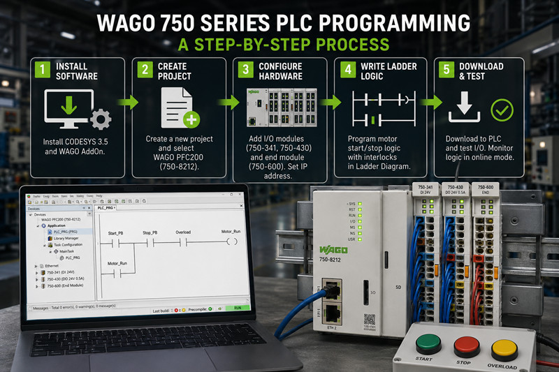
· WAGO 750-8212 PFC200 controller (dual-Ethernet, 1 GHz Cortex-A8, 512 MB RAM)
· WAGO 750-341 4-channel digital input module (24 VDC sink/source)
· WAGO 750-430 4-channel digital output module (24 VDC, 0.5 A per channel)
· WAGO 750-600 end module (mandatory bus termination — system will not power without it)
· 24 VDC power supply (Class 2 supply for UL-compliant installations)
· Ethernet cable, straight-through Cat5e
· Windows PC (CODESYS does not run on Linux or macOS)
Software
· CODESYS 3.5 SP19 or later (download from the CODESYS Store or WAGO website)
· WAGOAddOn for CODESYS (device description files for all 750-series controllers)
· A free CODESYS license works for initial programming. Production deployments need a runtime license ($150–$350 USD depending on feature tier).
Power: The 750-8212 accepts 24 VDC (20.4–28.8 VDC). For 120 VAC/60 Hz sites, use a WAGO 787-1622 DIN-rail supply. For 230 VAC/50 Hz installations, the WAGO 787-1661 fits. Both are CE and UL 508 listed.
1. Download CODESYS 3.5 SP19 from the CODESYS Store or the WAGO portal.
2. Run the installer as Administrator. Accept all defaults.
3. Download and install the WAGOAddOn for CODESYS package. This loads device descriptions for the 750-8212, 750-8202, 750-810, and all legacy controllers.
4. Launch CODESYS. Go to Tools → Device Repository and confirm WAGO PFC200 750-8212 appears in the list. If not, restart CODESYS and re-run the AddOn installer.
Common issue: Device description files are service-pack-specific. Installing AddOn for SP16 on CODESYS SP19 leaves you with zero devices listed. Match the AddOn version to your CODESYS service pack exactly.
---
5. Click File → New Project.
6. Select Standard Project.
7. Name the project `WAGO_Motor_Start_Stop`. Pick a save folder you will remember.
8. In the Device dropdown, select WAGO PFC200 (750-8212) . In PLC_PRG in, select Ladder Logic Diagram (LD) .
9. Click OK.
The workspace opens with the device tree on the left showing the controller and one POU named PLC_PRG.
---
Right-click WAGO PFC200 (750-8212) in the device tree and select Add Device.
· Add a WAGO 750-341 digital input module (bus address 1).
· Add a WAGO 750-430 digital output module (bus address 2).
· Add a WAGO 750-600 end module at the bus end (models the physical bus correctly in software).
ETHERNET vs fieldbus addressing: The 750-8212 uses ETHERNET for programming by default. If you integrate into a PROFIBUS network, you need a separate coupler (e.g., 750-375) and configure its address under the Fieldbus Configuration tab — not the Ethernet settings. First-time users frequently confuse the programming IP with the fieldbus station address. They live in different menus.
IP address: Double-click the controller node, go to the Ethernet tab, and assign a static IP — e.g., 192.168.1.10 with mask 255.255.255.0. Write this on the controller enclosure. You need it for every download.
Firmware check: Open the Information tab on the controller node. CODESYS 3.5 SP19 requires firmware v21 or later on the 750-8212. Controllers shipping with v18 or v19 need an update using the WAGO Firmware Update Tool (separate download) before your first program download. A firmware mismatch produces a silent failure — the download completes, the controller reboots, and the old program stays in memory.
---
Write a standard three-wire motor control circuit — the PLC equivalent of pushing a button to make something happen.
Open PLC_PRG. Declare these variables in the top pane:
`
PROGRAM PLC_PRG
VAR
Start_PB : BOOL; (* Start pushbutton — NO, 24 VDC *)
Stop_PB : BOOL; (* Stop pushbutton — NC, 24 VDC *)
Motor_Run : BOOL; (* Motor contactor output *)
Overload : BOOL; (* Thermal overload relay — NC *)
END_VAR
`
Map variables to I/O: Double-click WAGO 750-341 in the device tree. Map Start_PB to %IX1.0 (channel 0), Stop_PB to %IX1.1, Overload to %IX1.2. Then double-click WAGO 750-430 and map Motor_Run to %QX2.0. Alternatively, use the PLC_PRG I/O mapping table for a dropdown interface.
Ladder logic in CODESYS:
Drag contacts and coils from the Toolbox onto the rung. Build two rungs.
Rung 1 (seal-in):
`
Start_PB Motor_Run
----| |----------------------( )----
Motor_Run
----| |----(parallel branch to Start_PB)
`
Rung 2 (stop and overload in series):
`
Stop_PB Overload Motor_Run
----|/|----------|/|-----------( )----
`
Right-click contacts to toggle between normally-open (| |) and normally-closed (|/|). Add a parallel branch by right-clicking below the Start_PB contact and selecting Add Branch.
The logic reads: pressing Start_PB energizes Motor_Run. Motor_Run seals itself in through its own NO contact. Pressing Stop_PB or tripping Overload breaks the circuit and drops Motor_Run. This three-wire pattern translates directly to physical motor starter wiring — you can test the PLC against a real contactor without modifying the code.
---
10. Connect the 750-8212 to your PC with the Ethernet cable.
11. Power the controller. The RUN and I/O LEDs flash during boot. Wait for a steady RUN LED (about 30 seconds).
12. In CODESYS, click Online → Login (or press F11).
13. At the Select Network Path prompt, click Scan Network. The controller appears as `WAGO PFC200 (750-8212) @ 192.168.1.10`. Select it and click OK.
14. Click Yes to download the application.
15. The controller enters RUN mode automatically after the download completes.
16. Switch to Online → Toggle Watch View (F9). Ladder rungs highlight green when contacts and coils are active.
Test sequence:
· Momentarily short pin 1 (Start_PB) to 24 VDC on the 750-341. `Start_PB` turns green in the watch view and `Motor_Run` energizes.
· Momentarily short pin 2 (Stop_PB) to 24 VDC. `Stop_PB` turns green and `Motor_Run` drops out.
· Repeat with pin 3 (Overload) to confirm the interlock holds.
If Motor_Run does not energize, check wiring polarity on the 750-430 — outputs are sink/source configurable via the common terminal.
---
17. Firmware mismatch. You download the program, CODESYS says "Application downloaded successfully," the controller reboots, and nothing runs. The firmware on the 750-8212 is older than the project requires. Check the Information tab against your CODESYS SP compatibility matrix. Update firmware before the first download.
18. End module missing. Without the 750-600, the internal bus never initializes. The I/O LED flashes red. Fit the 750-600 at the right end of the DIN-rail assembly.
19. Subnet mismatch. CODESYS scans the local subnet only. PC on 192.168.0.x, controller on 192.168.1.10 — the scan finds nothing. Match subnets or add a secondary IP on your PC's adapter.
20. Wrong I/O mapping. Verify Start_PB maps to %IX1.0 (750-341, channel 0) and not %IX1.1. A swapped bit reads the wrong pushbutton. Use the I/O Mapping tab on each bus coupler node.
21. Expired trial license. CODESYS runtime on the 750-8212 runs in trial mode for 2 hours. After that, the controller stops executing user code. Purchase a runtime license ($250–$350 USD for the PFC200) and activate it via the CODESYS License Manager before commissioning.
---
· CODESYS 3.5 installed with matching WAGO AddOn version
· Controller firmware updated to v21 or later
· Static IP assigned and written down
· 750-600 end module fitted on the DIN rail
· I/O modules added in the device tree in correct bus order
· Variables declared and mapped to the correct bus addresses
· Ladder logic compiles without errors (green checkmark in Messages pane)
· PC and controller on the same subnet
· Login successful — green triangle in the status bar
· Pushbutton test passes: Start energizes, Stop drops, Overload holds
· Runtime license activated or trial timer noted
Next steps: Add analog modules (750-455, 750-456) for sensor feedback. Configure the second Ethernet port on the 750-8212 for plant network isolation. Set up a WebVisu dashboard for remote monitoring. Implement Modbus TCP master/slave to talk to a VFD.
For all WAGO 750 series parts — controllers, I/O modules, power supplies, and accessories — check current stock and pricing at tztechio.com/plc. We carry new and certified pre-owned WAGO automation hardware with CE and UL marks, ready to ship.
--------------------------------------------------------------------------------------------------------------------
🏢 About TZ Tech
TZ Tech is a leading supplier of industrial automation, electrical, instrumentation, and telecommunications components. We specialize in sourcing ready-to-ship distributor stock, allowing us to offer highly competitive pricing and short lead times. Thanks to our extensive inventory, we can even source rare and discontinued parts that are hard to find elsewhere.
🛡️ Our Quality Commitment
We understand that quality is your top priority. Every component undergoes a strict screening and inspection process so you can buy with absolute confidence. For legacy or discontinued parts, we believe in complete transparency and will always provide an honest, accurate report on the product's condition. Plus, all brand-new parts come backed by a full 1-year warranty.
✉️ Get in Touch
Have a project or a part you need? Send us your inquiry today! Our team is dedicated to providing a fast response within 6 hours (excluding weekends).


Please read on, stay posted, subscribe, and we welcome you to tell us what you think.


Sitemap | Blog | XML | Privacy Policy
In addition, with your permission, we want to place cookies to make your visit anointeraction with slOC more personal. For this we use analytical and advertisingcookies. With these cookies we and third parties can track and collect yourinternet behawior inside and outside super-instrument.com. With this we and third parties adapt super-instrument.com and advertisementsto your interest. By clicking Accept you agree to this. If you decline, we only usethe necessary cookies and you unfortunately will not receive any personalizedcontent. Please visit our Cookie policy for more information or to change yourconsent in the future.
Accept and continue Decline cookies