
Siemens S7-300 PROFIBUS DP Communication Faults: A Technical Guide
PROFIBUS DP is a master-slave fieldbus whose physical layer is RS-485. Communication faults on an S7-300 network are best classified by the layer at which they occur: physical, data link, or application. A steady red LED on the CPU's DP interface usually means a cable or termination problem; a configuration error in STEP 7 usually means a GSD or module-order problem. This guide defines the architecture, analyzes each layer, and closes with diagnostics and a spare-part strategy for a discontinued platform.
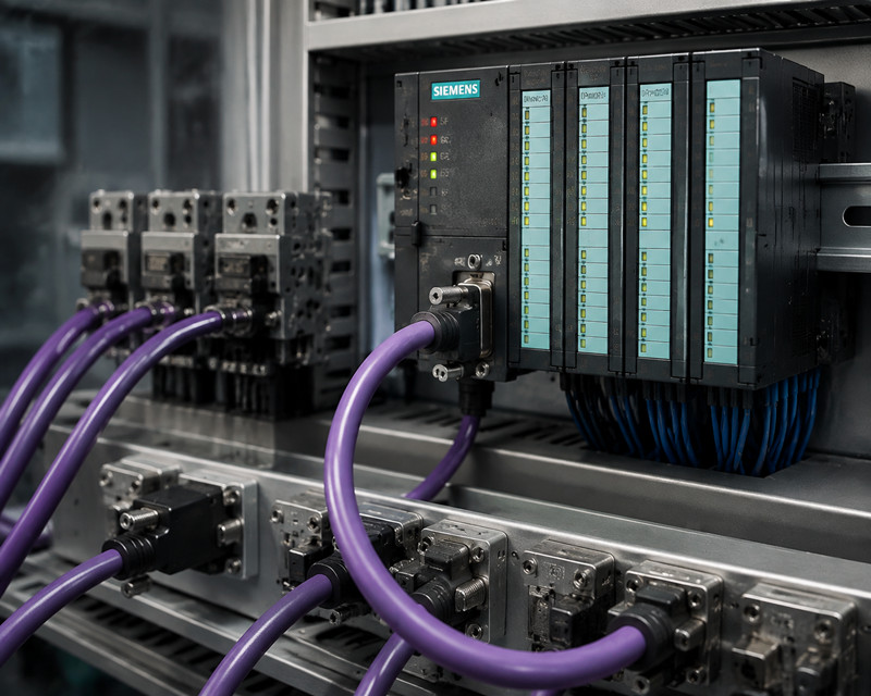
PROFIBUS DP (Decentralized Periphery) is a deterministic fieldbus standardized in IEC 61158 and IEC 61784. A class 1 master controls the bus cycle: it sends output data to each configured slave and receives input data in return within a fixed cycle time. Slaves are passive; they respond only when addressed. In the single-master systems that cover most S7-300 plants, the master polls its slaves in a fixed sequence.
Three protocol versions exist. DP-V0 provides the cyclic data exchange that nearly every S7-300 installation uses. DP-V1 adds acyclic read and write services and alarm handling, which intelligent slaves such as the IM 153-1 use for parameterization and channel diagnostics.
The electrical layer is RS-485 with differential signaling: the B line (RxD/TxD-P) and the A line (RxD/TxD-N) carry the same signal with opposite polarity, and the receiver evaluates the difference. Above it sits the FDL (Fieldbus Data Link) of layer 2, which frames telegrams and administers addresses. A fault must be assigned to its layer before it can be fixed.
Three devices fill the DP master role. The CPU 315-2 DP (6ES7 315-2AG10-0AB0) has an integrated DP interface with its own SF and BF LEDs, supports DP-V0 and DP-V1, and is the most common master in existing plants. The CPU 319-3 PN/DP (6ES7 318-3EL01-0AB0) adds PROFINET interfaces and the largest memory of the family; its DP interface behaves identically from the network's point of view. The CP 342-5 (6GK7 342-5DA02-0XE0) is a communications processor with its own microprocessor, RUN/STOP/BUSF LEDs, and master, slave, or combined operation; it offloads the bus from the CPU and exchanges data through the I/O area or via FC 1 (DP_SEND) and FC 2 (DP_RECV). Siemens PLC spares for all three masters remain in circulation.
The ET 200M uses the same S7-300 signal modules as the central rack. Its interface module, the IM 153-1 (6ES7 153-1AA03-0XB0), carries two decimal rotary switches for the station address and accepts up to eight modules. The ET 200S (interface module IM 151-1) sets its address with a single rotary switch. The ET 200pro (IM 154-1) is the IP65/67 variant mounted directly on the machine, and it is the most frequent source of intermittent connector faults in practice: vibration, moisture, and temperature cycling.
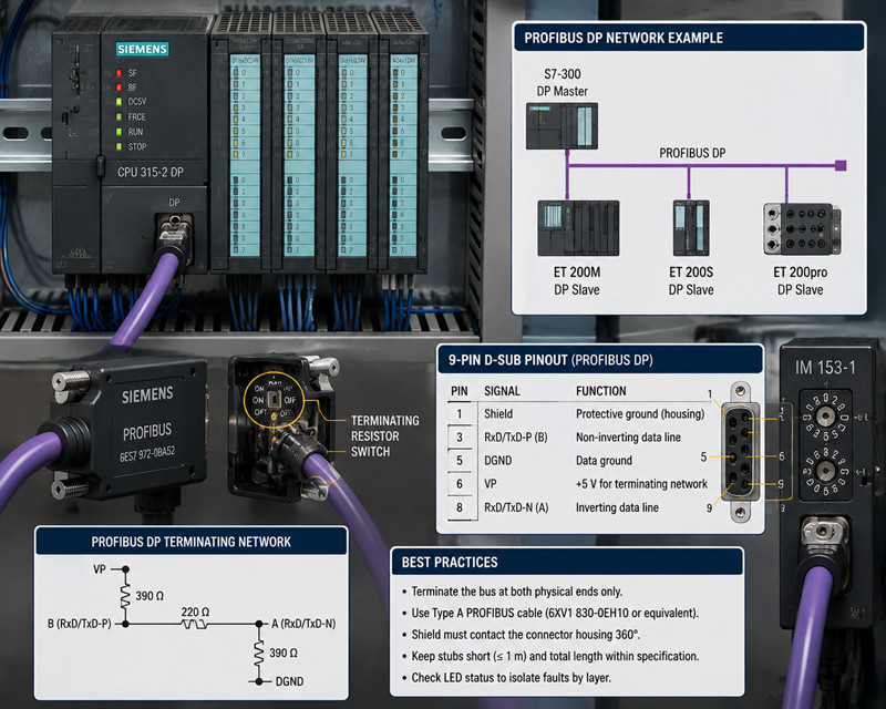
PROFIBUS connectors are active components of the bus. The 6ES7 972-0BA52 includes a PG socket that lets a programming device tap the bus without interrupting traffic; the 6ES7 972-0BB52 omits it. Both contain a built-in terminating resistor with a switch: when ON, the connector applies the terminating network and disconnects the outgoing cable, so a terminated connector must sit on the last station of a segment. PLC spares catalogs list both connectors.
The cable is a shielded twisted pair. Type A cable, the only type recommended for new installations, has a 0.34 mm² conductor, a characteristic impedance of 135 to 165 ohms at 3 MHz, and a braided shield with at least 80 percent coverage. The standard Siemens FC cable, 6XV1 830-0EH10, meets this specification. The shield must make low-impedance contact with the connector housing over the full circumference.
Every DP interface uses the 9-pin D-sub connector. The pins that matter for fault analysis are:
Pin | Signal | Function
1 | Shield | Protective ground, bonded to the connector housing
3 | RxD/TxD-P | B line, non-inverting data
5 | DGND | Data ground
6 | VP | +5 V supply for the terminating network
8 | RxD/TxD-N | A line, inverting data
Pins 2, 4, 7, and 9 carry auxiliary signals not required for DP operation. Verify the A and B conductors against pins 8 and 3 respectively; a reversed pair produces a dead segment.
An RS-485 bus must be terminated at both physical ends only. The PROFIBUS terminating network is a 390 ohm resistor from VP to B, a 220 ohm resistor between B and A, and a 390 ohm resistor from A to DGND. The 220 ohm resistor in parallel with the two 390 ohm resistors in series yields about 171 ohms, close to the 150 ohm cable impedance, so the line end absorbs the signal instead of reflecting it. The bias holds the idle state at a defined level: B at least 200 mV positive with respect to A. Without it, the receiver inputs float and the bus produces spurious telegrams. Termination must be powered: when the end station of a segment is switched off, its termination disappears, and the segment behaves erratically.
The baud rate sets the maximum segment length because the signal rise time and round-trip delay must fit within the bit time. The master sets the rate; slaves detect it automatically. Permitted combinations are:
Baud rate | Maximum segment length
9.6 kbps | 1200 m
19.2 kbps | 1200 m
45.45 kbps | 1200 m
93.75 kbps | 1200 m
187.5 kbps | 1000 m
500 kbps | 400 m
1.5 Mbps | 200 m
3 Mbps | 100 m
6 Mbps | 100 m
12 Mbps | 100 m
These figures assume type A cable, correct termination, and no more than 32 stations per segment. The practical failure at high baud rates is not length but the accumulated capacitance of connectors and stubs; at 12 Mbps even a 0.3 m stub distorts the signal, while at 9.6 kbps a short stub is harmless.
The RS-485 repeater 6ES7 972-0AA01 regenerates the signal and provides galvanic isolation between its two segments. It is required when a segment exceeds 32 stations or the length limit, and recommended when two cabinets have different ground potentials. Each repeater counts toward the 32-station limit, and up to nine may be connected in series, yielding ten segments. A repeater terminates both of its ports.
The shield is the primary defense against electromagnetic interference, and variable-speed drives are its primary source in most plants. Ground the shield at both ends through the connector housing; a one-ended shield still attenuates capacitive coupling but leaves the network exposed to magnetic fields. Use repeaters or equipotential bonding conductors where ground potentials differ. A DP cable must not run parallel to power cables; keep a separation of at least 20 cm and cross power cables at right angles.
Every station occupies an address between 0 and 126; address 0 is reserved for the programming device and 127 is the broadcast address, so DP stations use 1 to 125. On the IM 153-1 the address is set with the two rotary switches (tens and units), limiting the range to 1 through 99, and it is read at power-up. A duplicate address takes both stations out of service; an address of 0 has the same effect. The master's bus parameters (target rotation time, slot time, responder delays) are generated by STEP 7 from the station list and baud rate. They are not a tuning point, but they explain why a slave that works on a test bench fails on the plant network: the network's timing, not the slave, is at fault.
Baud rate detection is precise: slaves detect the rate from the first valid telegrams they receive. There is no baud rate switch on a DP slave, and two baud rates cannot run on one network. The GSD file records which rates a slave supports; a slave that does not support the configured rate never enters data exchange. industrial automation parts suppliers see this fault class regularly, because replacement slaves with different firmware sometimes carry a narrower baud rate range.
The GSD (Geräte-Stammdaten, device master data) file is the slave's identity card: a text file describing the manufacturer and ident number, supported baud rates, DP-V0/DP-V1 features, and the catalog of slotable modules. STEP 7 reads it to display the slave in the hardware catalog and to generate the configuration telegram sent at startup. The startup sequence explains the fault classes: the master sends Set_Prm (set parameters) and Chk_Cfg (check configuration) telegrams, and a slave that rejects either reports a configuration fault and never enters data exchange. It then appears online as present but faulty, which distinguishes this class from a physical failure. An old GSD version for a newer interface module produces the same symptoms; when a replacement IM 153-1 arrives with different firmware, compare its GSD with the project before commissioning.
For the ET 200M, the physical module order must match the configuration. The IM 153-1 addresses modules by slot; a 32-channel module where the project expects a 16-channel module makes the slave detect a mismatch and withhold its I/O, so the master reports it faulty although the station is electrically present. The ET 200S behaves the same way.
DP-V0 covers cyclic I/O exchange and the basic diagnostics that SFC 13 reads. DP-V1 adds acyclic services (SFB 52 RDREC, SFB 53 WRREC) and alarms (SFB 54 RALRM). A project configured for DP-V1 that meets a slave whose GSD supports only DP-V0 falls back to the lower service level; the failure appears when the application calls a DP-V1 function the slave cannot answer. That is a configuration fault, not a hardware fault.
Faults fall into three classes, and the class determines the diagnostic route.
The master reports a station failure and the slave never enters data exchange. Causes, in order of frequency: the slave is powered off; the address is wrong or duplicated; termination is missing at one end; a cable or connector is broken; the baud rate is not supported; the GSD or module configuration does not match. The fault is persistent and repeatable, which makes it the easiest class to isolate.
The slave drops offline for seconds or minutes and returns on its own, or the network fails only when a drive starts. Causes are physical: a loose connector, a shield not clamped, a moved termination switch, a cable routed with power cables, a corroded contact in a humid environment, or a segment operating marginally at its baud rate. Intermittent faults are the most expensive to chase because the network is healthy when the technician arrives; they require the recording tools described below.
The network is electrically healthy and every station is present, but the master and slave disagree about the configuration: GSD version, module order, firmware revision, or DP-V1 features. The slave reports a configuration fault in its diagnostics, which separates this class from the physical classes.
The front LEDs are the first diagnostic instrument, read in pairs: the master's and the slave's LEDs together localize a fault to one side of the bus.
LED | State | Meaning
CPU DP interface BF | off | Bus operation normal
CPU DP interface BF | flashing, 1 Hz | Interface cannot participate: address 0 or duplicate, no bus parameters
CPU DP interface BF | steady | A configured slave is not reachable: cable break, slave off, wrong slave address
CPU DP interface SF | on | A slave has signaled a diagnostic interrupt; clears when the diagnostics are fetched and the cause is removed
CP 342-5 RUN | green, steady | CP in RUN
CP 342-5 RUN | green, flashing | Startup phase
CP 342-5 STOP | yellow, steady | CP in STOP
CP 342-5 BUSF | flashing, 1 Hz | CP cannot participate: address 0 or duplicate, no termination, cable break at the CP
CP 342-5 BUSF | steady | Configured DP slaves cannot be addressed
A master with a steady BF LED and a slave with a healthy power LED points to the cable between them. A master whose BF LED flashes with an empty bus points to its own address or bus parameters. The MPI interface uses the same 9-pin connector and RS-485 level but a different protocol; its status is not shown by the BF and SF LEDs described here.
STEP 7 reads the DP master's diagnostics without programming. Open the online hardware configuration, select the DP master, and call PLC > Module Status. The DP slave diagnostics tab lists every configured station as data exchange, waiting, or faulty; the bus diagnostics view shows which stations are present and at which baud rate the network actually runs. If the station lists differ, the fault is physical; if they match and the slave still reports faulty, the fault is in configuration or diagnostics.
SFC 13 (DPNRM_DG) reads a slave's diagnostic telegram from the application program. Parameters: LADDR, the slave's diagnostic address from the hardware configuration; RET_VAL; RECORD, the data area receiving the diagnostics; and BUSY, indicating the call must be repeated. The record begins with a six-byte standard header: station status 1 to 3, the master address, and the manufacturer's ident number. Station status 1 separates the fault classes: bit 0, station does not exist; bit 1, not ready; bit 2, configuration fault; bit 6, device type mismatch. The device-specific part follows: which slot reported the fault and, for channel faults, the channel number and error code, such as error code 9 for a wire break on an analog input.
FB 125 (PO_DIAG) decodes the diagnostics of all slaves of a DP master system into a structured data block and is called from OB 82, OB 86, and OB 122. The result identifies the slave by address and classifies the fault: station failure, module fault, or channel fault with slot and channel number. An HMI or logging function can read the block, which turns an intermittent fault into a recorded event correlated with the machinery that was running.
OB 82 (diagnostic interrupt) fires when a slave reports module or channel diagnostics. OB 86 (rack failure) fires when a slave leaves the network; event ID 0xC4 identifies a station failure, 0xC1 a failure of the DP master itself. OB 122 (I/O access error) fires when the program accesses the I/O of a slave not in data exchange. A plant that runs these blocks empty loses the only record of what happened while nobody was watching; a minimal OB 86 that stores the event ID, timestamp, and faulty station address pays for itself at the first unexplained outage.
Symptom | Likely cause | Check | Fix
Slave never appears online; master BF steady | Cable break or connector unplugged | Measure continuity of A and B through the connectors | Replace the cable segment or reseat the connector
Slave appears, then drops when a drive starts | EMC coupling through the shield or cable route | Inspect shield clamping and the distance to power cables | Reground the shield; reroute the cable; add a repeater
Two stations drop simultaneously | Duplicate address | Compare the address switch settings with the address list | Set unique addresses and power-cycle both stations
Slave never enters data exchange; switches read 0 | Address set to 0 | Inspect the rotary switches | Set an address between 1 and 99 and power-cycle
Frame errors and drops at 12 Mbps | Segment too long or too many stubs | Measure the cable length; count the connectors | Lower the baud rate or add a repeater
Configuration fault on an ET 200M | Module order mismatch | Compare the physical modules with the HW Config slots | Align the module order or correct the project
Slave reports the wrong device type | GSD version mismatch | Compare the GSD in the project with the module firmware | Install the matching GSD; update the IM firmware
Network dead after a connector replacement | Termination switch moved | Inspect the termination switches at both ends | Set termination ON at both ends only
Intermittent drops in a humid area | Corroded contacts | Inspect the pins; measure the contact resistance | Replace the connectors
Master BF flashing with an empty bus | Master address 0 or duplicate | Check the master address in HW Config | Correct the address and download the hardware configuration
The following sequence resolves the majority of DP faults in under an hour.
1. Record the LEDs: the master's BF and SF, and the power and bus LEDs of every slave on the suspect segment.
2. Establish the baseline: open STEP 7 online, read the bus diagnostics, and confirm the actual baud rate and station list.
3. Check the physical layer: both termination switches, the connector latches on both ends of the suspect segment, and the address switches.
4. Isolate by halves: with the bus powered down, disconnect the middle connector and terminate both halves. The healthy half starts, the faulty half does not. Repeat until the fault is contained in one cable section.
5. For intermittent faults, install FB 125 with OB 82, OB 86, and OB 122, and let the network run until the next event. The recorded event identifies the station; the timestamp identifies the machinery in operation.
6. Measure a suspect cable: continuity of A and B, no short between them, shield continuity, and insulation to ground. The loop resistance of type A cable is about 110 ohms per kilometer; a value well above this indicates a damaged conductor.
7. Document every change. A DP network fault is often the result of a previous undocumented change.
· Verify the termination switch positions at both ends of every segment quarterly, and record them.
· Check the connector screws and cable clamps during scheduled outages; a loose clamp breaks the shield contact.
· Inspect the cable route whenever new drives or power cables are installed, and enforce the 20 cm separation.
· Read the bus diagnostics in STEP 7 during a scheduled stop and compare the station list with the address documentation.
· Check the cabinet ground connections and the equipotential bonding between cabinets.
· Keep a log of GSD versions and interface module firmware revisions, and record every hardware change.
· Test spare connectors and spare interface modules on a bench network before they are needed.
· Re-verify the bus parameters after any hardware configuration change; a re-download with a different baud rate changes the behavior of the entire network.
Siemens ceased production of the S7-300 in October 2025 and has committed to supplying spare parts until approximately 2033. A decade of operation remains for most plants, and the components that fail first on a PROFIBUS network are mechanical: connectors, cables, and interface modules. The bus connector 6ES7 972-0BA52, the IM 153-1, and the CP 342-5 are the parts a maintenance store should hold, together with a spare segment of FC cable. Siemens PLC spares that cover the DP layer cost little compared with a production stop caused by a connector that cannot be replaced, and Siemens S7-300 parts remain available through the same channel. The rule is simple: the network that carries the last S7-300 in the plant must outlive the CPU it serves.
Why does a DP slave drop offline randomly and return by itself?
The fault class is intermittent, and the cause is almost always physical: a marginal termination, a shield contact that opens with vibration, a corroded pin, or EMC coupling from a drive that starts at the same time each day. Install FB 125 with OB 86 so every drop is recorded with a timestamp, then correlate the timestamps with the machinery in operation. A drop that always coincides with a specific drive starting is an EMC problem; one that correlates with nothing is usually a connector or termination problem.
What does bus termination actually do?
The terminating network at each end of a segment performs two functions. The 220 ohm resistor between A and B, in parallel with the two 390 ohm resistors, matches the cable's characteristic impedance so the signal is absorbed at the end instead of reflected back into the bus. The 390 ohm bias resistors hold the idle state at a defined level: B at least 200 mV positive with respect to A. Both ends must be terminated, and the termination must be powered.
Can I mix baud rates on one network?
No. The master defines one baud rate for the entire network, and every slave must support it. Slaves detect the rate automatically, but a slave whose GSD does not list the configured rate never enters data exchange. Two different baud rates require two separate DP networks or two masters.
How long can a segment be?
Up to 1200 m at 9.6 to 93.75 kbps, 1000 m at 187.5 kbps, 400 m at 500 kbps, 200 m at 1.5 Mbps, and 100 m at 3 to 12 Mbps, assuming type A cable and correct termination. With up to nine repeaters in series, ten segments can be connected, and the total cable length is the sum of the segment lengths.
Do I need a repeater?
You need one when a segment exceeds 32 stations, when the cable length exceeds the limit for the baud rate, or when two cabinets have different ground potentials. The repeater 6ES7 972-0AA01 regenerates the signal, provides galvanic isolation, and terminates both of its ports. Up to nine repeaters may be connected in series.
The master reports a station failure, but the slave's power LED is on. Where do I start?
The slave is powered but not participating. Check the address switches (a duplicate address or an address of 0 takes a station off the bus), the termination at both ends of the segment, and the cable between the master and the slave. Then read the slave's diagnostics with SFC 13 or from the STEP 7 online view; station status 1 distinguishes a station that is not present from one that reports a configuration fault.
Can I replace an IM 153-1 with a newer revision without changing the project?
Usually, yes, provided the GSD in the project supports the features of the new firmware. Compare the GSD version with the module's firmware revision, install the matching GSD if necessary, and verify in the online diagnostics that the slave accepts the configuration. The module order in the rack must still match the project.
URL Slug: siemens-s7-300-profibus-dp-troubleshooting

Please read on, stay posted, subscribe, and we welcome you to tell us what you think.


Sitemap | Blog | XML | Privacy Policy
In addition, with your permission, we want to place cookies to make your visit anointeraction with slOC more personal. For this we use analytical and advertisingcookies. With these cookies we and third parties can track and collect yourinternet behawior inside and outside super-instrument.com. With this we and third parties adapt super-instrument.com and advertisementsto your interest. By clicking Accept you agree to this. If you decline, we only usethe necessary cookies and you unfortunately will not receive any personalizedcontent. Please visit our Cookie policy for more information or to change yourconsent in the future.
Accept and continue Decline cookies