Siemens S7-300/400 Memory Concept Explained: Load Memory, Work Memory, and Retentive Data
Aug 18, 2026
The memory architecture of the Siemens S7-300 and S7-400 programmable logic controllers is organized into three distinct layers: load memory, work memory, and system memory. Every memory-related fault, whether a CPU that refuses to leave STOP, a program that disappears after a power outage, or a battery alarm on an S7-400, can be traced back to one of these layers and to the rules that govern how data moves between them. This article defines each layer precisely, explains how the two controller families implement them differently, provides the concrete parameters of representative CPUs, and closes with failure diagnostics, maintenance practice, and the questions that engineers most frequently search for. The material assumes a working knowledge of STEP 7 and of the general structure of a PLC program, but no prior specialization in memory management.
1. The Three Memory Layers Defined
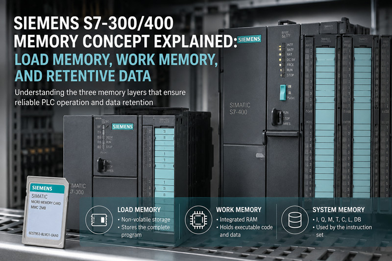
Load memory holds the complete user program, including code blocks (OB, FB, FC), data blocks (DB), symbols, comments, and technology data. It is the non-volatile, or battery-backed, repository from which the CPU restores its working copy at every startup. Work memory is the integrated RAM area in which the CPU actually executes the program; it contains only the code and data required for execution. System memory is the set of address areas that the instruction set operates on: process inputs (I), process outputs (Q), bit memory (M), timers (T), counters (C), local data (L), and data blocks (DB).
The distinction between the three layers is not academic. A block that exists only in load memory is not executed. A block that exists only in work memory is executed but cannot be uploaded to a programming device. A retentive flag that is not backed up in load memory is reset at every restart. Each layer has its own volatility, its own capacity limits, and its own failure behavior, as summarized in Table 1.
Table 1: The three memory layers at a glance
Layer | Contents | S7-300 implementation | S7-400 implementation | Behavior on power loss
Load memory | Full program: blocks, symbols, comments, technology data | Micro Memory Card (MMC) | RAM backed by battery; optional Flash EPROM card | S7-300: retained on the MMC. S7-400: retained in RAM while the battery is healthy; otherwise restored from EPROM or lost
Work memory | Executable code and data only | Integrated RAM | Integrated RAM | Contents lost; rebuilt from load memory at the next startup
System memory | I, Q, M, T, C, L, DB addressing | Internal CPU circuitry | Internal CPU circuitry | Non-retentive parts reset; retentive parts restored from load memory
A second axis runs through the architecture: the difference between volatile and non-volatile storage. On the S7-300, non-volatility is achieved with flash memory (the MMC) and no battery is required. On the S7-400, non-volatility is achieved with a battery-backed RAM and, optionally, with a Flash EPROM card. This single difference explains most of the practical divergence between the two families, from the battery-low LED on the S7-400 to the fact that an S7-300 CPU without an MMC will not start at all.
2. Load Memory: Where the Program Is Stored
Load memory is the highest-capacity layer. It stores the program in its complete form, including data that the CPU never executes directly: block comments, symbol information, and technology objects. When a project is compiled and downloaded, every block is transferred into load memory first. The CPU then copies the executable portions into work memory. Because load memory holds the full project, it is also the layer that an upload reads when you transfer a program from a CPU back to a programming device.
2.1 Load memory on the S7-300: the Micro Memory Card
All current S7-300 CPUs store load memory on a Micro Memory Card (MMC). The MMC is a plug-in flash card that fits into a slot on the front of the CPU. It requires no battery, which is why an S7-300 plant can sit without power for years and still start with its program intact. Representative order numbers for the MMC family are 6ES7953-8LL31-0AA0 (512 KB) and 6ES7953-8LM31-0AA0 (2 MB); the same family extends from 64 KB up to 8 MB, and the maximum acceptable size depends on the CPU.
The MMC is not an optional accessory. A modern S7-300 CPU without an MMC cannot run a program: the CPU goes to STOP and requests a memory card in the diagnostics buffer. This is a deliberate design decision. Because the MMC is the only non-volatile storage in the system, it holds not only the program but also the retentive data and, on some CPUs, the firmware. If the card is missing, the CPU has neither a program to execute nor a place to store retentive state.
The MMC carries a small write-protection slider on its housing. When the slider is in the locked position, the CPU rejects downloads with a message stating that the memory card is write-protected. The slider protects the card against accidental overwrite in the field, but it is a common cause of failed downloads after maintenance, so its position should be the first thing checked when a download is refused.
If load memory is lost or empty: on the S7-300, an empty or missing MMC means the CPU stops and cannot start. On the S7-400, an empty RAM load memory with no EPROM card means the CPU starts into STOP with no user program; if an EPROM card is present, the CPU copies the program from the EPROM into RAM at startup and runs normally.
2.2 Load memory on the S7-400: battery-backed RAM and Flash EPROM
The S7-400 implements load memory in two stages. The primary stage is RAM integrated on the CPU module, which holds the working copy of the load memory. This RAM is kept alive by a backup battery, for example 6ES7971-0BA00, mounted in the power supply or in the CPU compartment. The secondary stage is a plug-in Flash EPROM card, for example 6ES7952-1KM00-0AA0, which provides non-volatile storage that survives even a complete loss of battery power.
At power-up, the S7-400 behaves as follows. If the RAM load memory contains a program, the CPU copies it into work memory and starts. If the RAM is empty but a Flash EPROM card is inserted, the CPU copies the program from the EPROM into the RAM load memory and then into work memory. If both are empty, the CPU goes to STOP. This startup chain is the reason why a well-maintained S7-400 can recover from a battery failure without any intervention, provided the EPROM was kept up to date.
If load memory is lost or empty: on the S7-400, loss of the RAM load memory occurs when the battery fails during a power outage and no EPROM card is fitted. The program is then gone and must be re-downloaded or restored from a backup file. This scenario, more than any other, justifies the habit of downloading to EPROM after every commissioning change.
3. Work Memory: The Execution Space
Work memory is the integrated RAM in which the CPU executes the program. It is divided internally into a code area and a data area. At download time, the CPU copies the executable blocks from load memory into work memory; at runtime, the CPU fetches instructions and data exclusively from work memory. Work memory is always volatile. On both families it is rebuilt from load memory at every power-on, so a program that "survives" a power cycle does so because load memory survived, not because work memory did.
Work memory is the layer that determines whether a program fits. A large data block, a long OB, or a heavily nested FB can exhaust work memory even when the load memory still has free space. When this happens, the download is rejected with a message such as "No user memory available," and the remedy is either to reduce the program size or to move to a CPU with more work memory. Work memory cannot be expanded by adding cards; it is a fixed property of the CPU module itself. This is why the work memory figure in the CPU technical data is the single most important number to check when a project outgrows its controller.
If work memory is lost or empty: the CPU stops or fails to start. Because work memory is rebuilt at every power-on, its loss is normally transient and invisible: the CPU simply reloads from load memory. The loss becomes permanent only when load memory is also lost, which is the S7-400 battery scenario described above.
4. System Memory and the Address Areas
System memory is the collective term for the addressable data areas that the instruction set operates on. These areas are implemented in the CPU's internal circuitry, not on any removable medium, and their sizes are fixed properties of each CPU model. Table 2 lists the areas and their roles.
Table 2: System memory address areas
Area | Symbol | Contents | Notes
Process image of inputs | I | Input states copied from the I/O modules at the start of each OB 1 scan | Byte and bit addressing, for example I0.0 through I0.7 in input byte IB0; default range 128 bytes, configurable up to a CPU-specific maximum (2048 bytes on most S7-300 CPUs)
Process image of outputs | Q | Output states written to the I/O modules at the end of each OB 1 scan | Byte and bit addressing, for example Q0.0 through Q0.7 in output byte QB0
Peripheral I/O | PI, PQ | Direct access to I/O modules that bypasses the process image | Used for high-speed or time-critical I/O; addressed as PIW/PQW words
Bit memory | M | Flags for intermediate logic states | Byte and bit addressing, for example M0.0 through M0.7 in flag byte MB0; size depends on the CPU; on some CPUs the first 256 bytes are reserved for system data and cannot be used freely
Data blocks | DB | Structured data storage for the user program | The Retain attribute controls whether DB contents survive a restart
Timers | T | S5 timer functions | Number of timers depends on the CPU
Counters | C | Counter functions | Number of counters depends on the CPU
Local data | L | Temporary variables of the currently active OB, FB, or FC call | Stack-based; depth is limited per priority class
4.1 The process image
The I and Q areas are refreshed through the process image. At the start of the cyclic program, the CPU copies the states of the input modules into the I area; during the cycle, the program reads these consistent snapshots; at the end of the cycle, the CPU copies the Q area to the output modules. This mechanism guarantees that all program sections see the same input states within one scan. Direct peripheral access (PIW, PQW) bypasses the image and reads or writes the module directly, which is faster but not consistent within the scan. A process image that is too small for the installed I/O can be enlarged in the CPU properties in STEP 7, up to the CPU-specific maximum.
4.2 Bit memory M and the flag byte
Bit memory, historically called flags, is the scratchpad of the program. A single flag bit, for example M0.0, holds one Boolean state; eight consecutive bits form flag byte MB0, addressed as M0.0 through M0.7. Flag words (MW) and flag double words (MD) are formed by grouping bytes. The size of the M area differs per CPU: a CPU 314 provides 256 bytes, a CPU 315-2 DP provides 2048 bytes, and a CPU 319-3 PN/DP provides 8192 bytes. On several S7-300 CPUs, part of the M area, for example the first 256 bytes, is reserved for system data used by the operating system and by system functions; using these addresses in the user program can produce erratic behavior, so the technical data of the specific CPU must be consulted before the M area is allocated freely.
4.3 Timers, counters, and local data
Timers (T) and counters (C) are functional elements with an internal state: a timer stores the remaining time, a counter stores the count value. Their numbers are fixed per CPU, for example 256 timers and 256 counters on a CPU 314 and 2048 of each on a CPU 319-3 PN/DP. Local data (L) is the stack area that holds the temporary variables of the currently active call. Every time an FB or FC is called, the CPU reserves a slice of the local data stack for that block's temporaries; deep nesting or large temporary structures can exhaust the stack, which produces a programming error and, if unhandled, a STOP. On S7-300 CPUs the local data stack is typically 32 KB shared across the priority classes; on S7-400 CPUs the capacity is larger and, on newer models, allocated per priority class.
If system memory is lost or reset: non-retentive I, Q, M, T, C, and L areas are initialized at every restart, and non-retain DBs are reset to their load values. Retentive areas are restored from load memory, which is the mechanism examined in the next sections.
5. The S7-300 in Practice: MMC, Retentive Data, and the Battery Question
The defining property of the S7-300 memory concept is the absence of a battery. The program lives on the MMC, work memory is reloaded from the MMC at every power-on, and retentive data is stored on the MMC as well. When the CPU detects a power-down, it saves the current values of the configured retentive areas to the MMC; at the next power-up, it restores them. This design has three practical consequences.
First, the MMC is a wear item in a narrow sense. Flash memory has a finite erase/write endurance, and every power-down writes the retentive areas. Under normal cyclic operation this is not a concern, but programs that modify retentive data in fast cycles, or that use the system functions SFC 82 to SFC 84 to write data blocks on the MMC in a loop, shorten the card's life. The rated number of write cycles is given in the Siemens documentation for the card.
Second, retentive configuration is explicit. In STEP 7, the CPU properties dialog (Hardware Configuration, Retentive Memory tab) defines how many bytes of M, how many timers, and how many counters are retentive. The default retentive flag range on most S7-300 CPUs is M 0.0 through M 15.7. Data blocks are made retentive individually by marking them with the Retain attribute in the block properties. Only the configured ranges survive a power cycle; everything else is initialized.
Third, the download behavior is simple and uniform. A normal download in STEP 7 writes the block to the MMC (load memory) and copies it into work memory. There is no separate "download to RAM only" path on the S7-300: with an MMC fitted, every download is automatically non-volatile. The upload direction works the same way: an upload reads from the MMC. Replacement MMC cards in all capacities are listed in the Siemens PLC spare parts catalog, which matters for plants that must keep a programmed spare card on the shelf.
The battery question, which dominates S7-400 discussions, simply does not arise on the S7-300. If an S7-300 CPU has no battery, the program cannot be lost to a battery failure. The realistic failure modes are a missing, full, write-protected, or defective MMC, and each of them is examined in Section 9.
6. The S7-400 in Practice: Batteries, EPROM, and the Startup Chain
The S7-400 memory concept is organized around battery-backed RAM, with the Flash EPROM as the safety net. The backup battery, for example 6ES7971-0BA00, maintains the RAM-based load memory and the retentive data while the controller is powered off. The CPU module also carries an integrated rechargeable buffer battery, which maintains the RAM for a limited time, on the order of tens of minutes when fully charged, during a main battery change. This buffer is the reason a battery can be swapped with the power off at all, but it must never be relied on for longer than the manual specifies.
The Flash EPROM card, for example 6ES7952-1KM00-0AA0, is the non-volatile layer of the S7-400. It is not required for operation, but it is the difference between a recoverable and a catastrophic battery failure. The card family spans from 64 KB up to 64 MB, and the maximum size depends on the CPU. The startup chain described in Section 2.2 means that a CPU with a current EPROM card recovers automatically from a flat battery; a CPU without one starts into STOP and needs a re-download.
Download behavior on the S7-400 has two levels, and confusing them is a common source of field problems:
1. A normal download writes the block to the RAM load memory and to work memory. The change is active immediately but is volatile: it survives a power cycle only while the battery keeps the RAM alive.
2. "Download to EPROM" (or "Copy RAM to ROM") writes the current load memory contents to the Flash EPROM card. The change then survives even a total battery loss.
The classic S7-400 failure sequence is therefore: download a modification in the afternoon, never copy RAM to ROM, and find two weeks later, after a power outage with a flat battery, that the CPU restarts with the old program from the EPROM. The modification existed only in RAM and was lost. Keeping the EPROM current after every commissioning change is the single most effective memory-related maintenance rule for the S7-400.
The S7-400 reports its battery state continuously. A battery-low condition lights the BATF LED on the front of the CPU or power supply and writes an entry to the diagnostics buffer. STEP 7 shows the detailed state in Hardware Diagnostics / Module Information on the Battery tab, which lists the battery status and, on many CPUs, the estimated remaining backup capacity. Backup batteries such as the 6ES7971-0BA00 are stocked in the PLC spare parts range precisely because they are a consumable with a service life measured in years, not decades.
7. Memory Sizing Reality per CPU
The practical question in every memory-related project discussion is the same: how much work memory and how much load memory does the CPU actually have? Table 3 gives representative figures for five widely installed CPUs. The work memory figure is fixed; the load memory figure is the maximum size of the MMC or EPROM card the CPU accepts.
Table 3: Representative CPUs and their memory
CPU | Order number | Work memory | Load memory (max) | Typical use
CPU 314 | 6ES7314-1AG14-0AB0 | 128 KB | MMC up to 8 MB | Medium machines, standard S7-300 applications
CPU 315-2 DP | 6ES7315-2EH14-0AB0 | 256 KB | MMC up to 8 MB | Distributed I/O via PROFIBUS DP
CPU 319-3 PN/DP | 6ES7318-3EL01-0AB0 | 2 MB | MMC up to 8 MB | Large S7-300 applications with PROFINET
CPU 414-2 | 6ES7414-2XK05-0AB0 | 512 KB | RAM plus EPROM up to 64 MB | Mid-range S7-400 applications
CPU 417-4 | 6ES7417-4XT05-0AB0 | 4 MB | RAM plus EPROM up to 64 MB | High-performance S7-400 applications
Two sizing rules follow from the table. First, work memory is the binding constraint for program logic. A project with large data blocks or many blocks in the cyclic path needs work memory headroom, because the CPU executes from work memory and cannot page code in from load memory on demand. Second, load memory is the binding constraint for project data: symbols, comments, and technology objects are stored only in load memory. A project that compiles to 300 KB of code may still need a 2 MB MMC once comments and symbol information are included. The general practice is to size the MMC generously at commissioning, because a card swap later requires a full download and a brief production stop.
8. Configuring Retentive Data
Retentive data is the state that must survive a power cycle: finished-part counters, recipe selections, mode flags, and accumulated totals. The configuration procedure is identical in structure on both families, with the storage mechanism differing underneath.
On the S7-300, open the CPU properties in Hardware Configuration and select the Retentive Memory tab. There, define the retentive ranges for bit memory (for example 16 bytes of M by default), the number of retentive timers, and the number of retentive counters. Data blocks are handled individually: in the DB properties, mark the block as Retain. Retentive data is then stored on the MMC at power-down and restored at power-up, which is why it survives without any battery.
On the S7-400, the same dialog defines the retentive ranges, but the storage mechanism is the battery-backed RAM. Retentive values survive a power cycle as long as the battery is healthy. If the battery fails while the controller is powered off, retentive data is lost and the affected DBs are reinitialized to their load values at the next startup. This is why the battery state of an S7-400 is a maintenance topic, not an operational detail.
Three configuration errors account for most retentive-data complaints. The retentive range is not configured at all, so flags reset at every restart. The range is configured but the DB lacks the Retain attribute, so DB contents reset even though M flags survive. Or the range is configured on the wrong CPU in a multi-CPU project, so the intended CPU resets while an unused one retains. All three are diagnosed in minutes by comparing the Retentive Memory tab with the observed behavior after a test power cycle.
9. Failure Modes and Diagnostics
Memory faults on the S7-300/400 present themselves through the LEDs, the diagnostics buffer, and the behavior of downloads and uploads. Table 4 collects the common failure modes, their causes, and the diagnostic path for each.
Table 4: Memory-related failure modes and diagnostics
Symptom | Likely cause | Diagnostic path | Remedy
CPU in STOP; SF and STOP LEDs lit; diagnostics entry "STOP due to memory error" | MMC missing or defective (S7-300), or load memory corrupt | Read the diagnostics buffer via STEP 7 (accessible nodes, module information); check the MMC seating | Insert a known-good MMC with a backup of the program; re-download; replace the card if defective
Download rejected with "No user memory available" | Work memory or load memory capacity exhausted | Compare project block sizes with the CPU work memory; check free load memory | Delete unused blocks; reduce DB sizes; move to a CPU with more work memory or a larger MMC
Download rejected with "memory card is write-protected" | MMC slider in locked position | Inspect the slider on the card housing | Open the slider; repeat the download
Download rejected on an S7-300 with no card inserted | MMC absent | Check the card slot; read the diagnostics buffer | Insert the MMC; the CPU then accepts the download
S7-400 BATF LED lit; diagnostics entry "battery low" | Backup battery exhausted or missing | Module Information, Battery tab; check voltage and status | Replace the battery per the procedure in Section 11; verify RAM contents afterward
S7-400 restarts with an older program after a power outage | Battery flat and EPROM card holds an older version than the last RAM download | Compare the EPROM date with the last commissioning change | Copy RAM to ROM / download to EPROM after every change; replace the battery
Upload returns no blocks or an incomplete project | Blocks exist only in work memory, or the MMC holds an older version (S7-300) | Attempt upload from the CPU; check which blocks are listed | Download the current program to the MMC first; then upload
Retentive data lost after a restart | Retentive ranges not configured, DB without Retain attribute, or MMC removed at power-down (S7-300) | Review the Retentive Memory tab; perform a controlled test power cycle | Configure the retentive ranges and Retain attributes; re-download
SFC 82/83/84 call reports "No user memory available" | MMC full or write cycle limit reached during runtime data logging | Check free MMC space; review the call parameters | Free space on the card; archive and delete old logged data blocks
Two general rules make these diagnostics faster. First, the diagnostics buffer is the primary evidence: it records the stop cause, the time stamp, and the module that triggered the event, and it is readable even from a CPU in STOP. Second, the distinction between load memory and work memory explains most upload/download surprises: if a block is not in load memory, it cannot be uploaded; if it is not in work memory, it cannot be executed.
10. Maintenance and Backup Practice
Memory maintenance on legacy S7-300/400 equipment follows a small set of rules that prevent nearly every failure mode in Table 4.
Back up before you touch. A full upload of the program and the Hardware Configuration to the engineering station should precede any download, any memory card operation, and any battery work. The backup file is the insurance that makes every subsequent step reversible. Many plants schedule a fresh backup after every commissioning change and keep the file on a server with the date in the file name.
Check the S7-400 battery on a schedule. The battery state is visible in STEP 7 Hardware Diagnostics / Module Information on the Battery tab, and the BATF LED gives a local indication. A monthly check of the BATF LED during routine rounds, plus a quarterly review of the Battery tab, catches a weak battery long before it becomes a production event. Battery service life is measured in years, but it varies with ambient temperature and the duration of power outages, so calendar-based replacement is less reliable than status-based replacement.
Handle MMCs by the book. The MMC may be inserted or removed only with the CPU powered off. Removing a card during operation, or during a download, can corrupt the card and forces a format and a full re-download. Cards should be stored in anti-static packaging, labeled with the project name and firmware version, and write-protected with the slider once the content is final. A programmed spare card on the shelf is the fastest disaster recovery an S7-300 plant can have; the Siemens PLC spare parts range covers the card family from 512 KB to 8 MB.
Think about the power supply. The S7-300 is fed by the PS 307 and the S7-400 by the PS 407, both available for 120 V/60 Hz and 230 V/50 Hz mains; the input range is printed on the type plate of each module. The modules carry CE marking for the European market and UL/CSA listings for North American installations. A failing power supply produces memory symptoms before it produces a total failure, because brown-outs corrupt RAM contents and trigger restart sequences. Voltage measurements at the load terminals belong in the same maintenance round as the battery check.
Stock spares for legacy plants. Plants running S7-300/400 hardware beyond its original service life should hold, at minimum, one programmed MMC per CPU type, one spare backup battery per S7-400, and one spare CPU of each type in use. Older CPUs are increasingly difficult to source, so the spare CPU should be procured while the type is still available. If the plant uses Flash EPROM cards, a spare card with the current program completes the set. The cost of a programmed card and a battery is small compared with the cost of an unplanned production stop, and prices in USD vary with region and availability.
11. Frequently Asked Questions
Does the S7-300 lose its program when the battery dies? No, because the S7-300 has no battery for program storage. The program resides on the MMC, and work memory is reloaded from the MMC at every power-on. A discharged battery is therefore not a cause of program loss on the S7-300; most S7-300 CPUs do not even have a battery compartment. The battery question applies to the S7-400, where the RAM-based load memory depends on the backup battery while the controller is powered off.
What happens if the MMC is removed while the CPU is running? The CPU can go to STOP, and the card itself can be damaged, because the CPU writes to the MMC at power-down and during downloads. Siemens specifies that the MMC may be inserted or removed only with the power off. If a card was removed while running, power the CPU down, reinsert the card, and check the diagnostics buffer. If the card was corrupted, format it and re-download the program from the backup.
How do I make data retentive on an S7-300? Open the CPU properties in Hardware Configuration and select the Retentive Memory tab. Define the retentive ranges for bit memory (default M 0.0 to M 15.7), the number of timers, and the number of counters. For data blocks, mark the block with the Retain attribute in its properties. The retentive data is then saved to the MMC at power-down and restored at power-up, without any battery. Note that only the configured ranges retain their values; everything else is initialized at restart.
What is the S7-400 battery change procedure? First, confirm that the current program is stored on a Flash EPROM card or in a backup file on the engineering station; this step is mandatory. Then, with the CPU powered on, open the battery compartment and replace the cell with a new one of the same type (6ES7971-0BA00), working within the buffer time provided by the integrated rechargeable battery, typically on the order of tens of minutes when fully charged. After insertion, confirm that the BATF LED extinguishes and verify the status in Module Information on the Battery tab. If the CPU was powered off and the RAM was lost, restore the program from the EPROM or from the backup before restarting production.
Can I download to work memory only? On the S7-300, no: with an MMC fitted, every download writes to the MMC and copies into work memory, so every download is automatically non-volatile. On the S7-400, a normal download writes to the RAM load memory and to work memory; the change is volatile unless you then download to the EPROM or copy RAM to ROM. A change that exists only in RAM survives a power cycle only while the battery keeps the RAM alive. If the battery fails during an outage, the change is lost and the CPU restarts with the EPROM version.
Why does my upload show no blocks? An upload reads from load memory. On the S7-300, blocks that exist only in work memory cannot be uploaded, which typically happens when the MMC was replaced or formatted after the last download. Download the current program to the MMC first, then perform the upload. On the S7-400, verify that the RAM load memory, not only work memory, contains the program; if the CPU was restarted from the EPROM after a battery loss, the upload returns the EPROM version.
How long does the S7-400 battery last, and when should it be replaced? The service life depends on the battery chemistry, the ambient temperature, and the frequency and duration of power outages. The reliable method is status-based replacement: replace the cell when the BATF LED lights or when Module Information reports a low state. In a powered-up rack, several years of service are typical. The rechargeable buffer battery on the CPU gives a limited window for a main battery change, so a replacement cell should be on hand before the procedure starts.
12. Summary
The S7-300/400 memory concept is a three-layer model. Load memory holds the complete program and is non-volatile (MMC on the S7-300, battery-backed RAM with optional Flash EPROM on the S7-400). Work memory is the volatile integrated RAM from which the CPU executes, and it is rebuilt from load memory at every startup. System memory provides the address areas I, Q, M, T, C, L, and DB, with retentive subsets configured in STEP 7 and restored from load memory at restart.
Most field problems reduce to a small number of causes: a missing or write-protected MMC on the S7-300, a flat battery or an outdated EPROM on the S7-400, a retentive range that was never configured, or a program that exceeds work memory. Each has a defined diagnostic path through the LEDs, the diagnostics buffer, and Module Information, and each has a defined remedy. The maintenance rules that prevent them are equally few: back up before any download, keep the EPROM current on the S7-400, check the battery on a schedule, handle MMCs only with the power off, and keep a programmed spare card and a spare battery on the shelf. For plants that run legacy S7-300/400 hardware, these rules are not optional diligence; they are the difference between a brief intervention and a full re-commissioning.
13. Maintenance Checklist
· [ ] Full program and Hardware Configuration backed up to the engineering station after every commissioning change
· [ ] MMC inserted in every S7-300 CPU; spare programmed MMC stored per CPU type (write-protect slider closed)
· [ ] MMC slider position verified before downloads; cards inserted and removed only with power off
· [ ] S7-400 BATF LEDs checked during routine rounds (monthly)
· [ ] S7-400 battery status reviewed in Module Information, Battery tab (quarterly); replacement battery in stock
· [ ] Flash EPROM cards up to date after every download (Copy RAM to ROM / download to EPROM)
· [ ] Retentive ranges and Retain attributes verified against the process requirements after any configuration change
· [ ] Retentive behavior confirmed with a controlled test power cycle after commissioning
· [ ] Diagnostics buffer reviewed periodically; unexplained entries investigated before they become stops
· [ ] Spare CPUs, MMC cards, batteries, and EPROM cards stocked for each CPU type in service
· [ ] PS 307 / PS 407 input voltage (120 V/60 Hz or 230 V/50 Hz) and output voltage verified at the load terminals
URL Slug: siemens-s7-300-400-memory-concept
---------------------------------------------------------------------------------------------
🏢 About TZ Tech
TZ Tech is a leading supplier of industrial automation, electrical, instrumentation, and telecommunications components. We specialize in sourcing ready-to-ship distributor stock, allowing us to offer highly competitive pricing and short lead times. Thanks to our extensive inventory, we can even source rare and discontinued parts that are hard to find elsewhere.
🛡️ Our Quality Commitment
We understand that quality is your top priority. Every component undergoes a strict screening and inspection process so you can buy with absolute confidence. For legacy or discontinued parts, we believe in complete transparency and will always provide an honest, accurate report on the product's condition. Plus, all brand-new parts come backed by a full 1-year warranty.
✉️ Get in Touch
Have a project or a part you need? Send us your inquiry today! Our team is dedicated to providing a fast response within 6 hours (excluding weekends).